КАТЕГОРИИ:
АстрономияБиологияГеографияДругие языкиДругоеИнформатикаИсторияКультураЛитератураЛогикаМатематикаМедицинаМеханикаОбразованиеОхрана трудаПедагогикаПолитикаПравоПсихологияРиторикаСоциологияСпортСтроительствоТехнологияФизикаФилософияФинансыХимияЧерчениеЭкологияЭкономикаЭлектроника
Angle of Bank Stalling Speed Load Factor mph IAS
| 0° | 1.0 | |
| 50° | 1.5 | |
| 60° | 2.0 | |
| 65° | 2.5 | |
| 70° | 3.0 |
4.7 WEIGHT AND BALANCE
LIMITATIONS
4.7.1 GENERAL
The Design Gross Weight of the aircraft is 5, 100 lb. At this weight it complies with the general performance and strength criteria.
In the interest of airworthiness it is important that the weight and balance limits for this airplane be adhered to in accordance with the recommendations and information given in the following paragraphs, tables and diagrams.
4.7.2 WEIGHT DEFINITIONS
The Tare Weight is the weight of the aircraft with the minimum equipment essential to airworthiness, e.g. pilot's seat, flight and engine instruments, battery and the like.
Hence equipment changes in the field will not normally change the tare weight figure.
The tare weight will be appropriate to the configuration, i.e. the landplane, ski- plane and seaplane values will differ.
The Basic Weight includes all other installed equipment both fixed and removable, e.g. radio, exterior finish (paint), furnishings and such equipment is defined by the item ticked off in the Weight and Balance Report under the heading "Equipment Check List" and "Basic Weight Change Record".
The Operational Load comprises crew, oil and fuel, and payload weights.
The Payload consists only of passenger (s), baggage and cargo. Maximum values of payload vs. range for various basic weights are given in the Appendix pages VI and VIA.
The All-Up Weight (A.U.W .) is the sum of basic weight plus operational load and must not exceed 5, 100 lbs. for the landplane and skiplane, 5,090 for the seaplane.
4.7.3 FUEL ALLOWANCES
It should be noted that fuel allowances are included for 10 minutes warm-up,
| + 50 |
| -200 |
| + 100 |
| -100 |
| -150 |
-250
| LEADING EDGE ♦ 17.5 I |
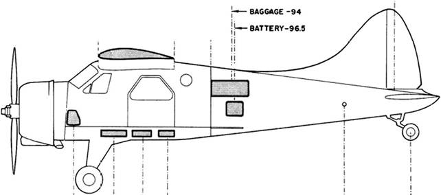
| TRAILING EDGE -45 |
| -M.A.C. 62.5 |
| BAGGAGE 8LKHD -76.5 |
RUDDER -230.9
| TAIL LIFT TUBE -188.6 |
| ♦ 4.5 |
| TAILWHEEL -244 |
| -196 |
FUEL TANKS

|
FIG 4-2 BALANCES DIAGRAM
take-off and climb to 5,000 ft. altitude, and reserve fuel for 45 minutes flying time at cruising power.
4.7.4 WEIGHT AND BALANCE
REPORT
This report defines the equipment that was in the aircraft "as weighed" and "as delivered" and gives weights, arms and movements as well as the Tare and Basic Moment. It may be found in the envelope on the inside of the rear cover of this Flight Manual.
If the equipment is changed, the Basic Weight changes too. Changes should be recorded in the "Basic Weight Change Record", which must be kept up-to-date at all times.
The "Equipment Check List" should be ticked off.
If the configuration of the aircraft is altered at any time, e.g. changing from floats to skis, such alterations must be duly recorded in the "Basic Weight Change Record".
The obligation that all changes must be recorded, applies also to modifications of all sorts, e.g. repair of damages suffered in the field, in which case all parts removed from,or added to, the aircraft must be separately weighed and their Moment Arms measured so that the "Weight and Balance Report" may be properly brought up to date.
The Balance Diagram (Figure 4-2), may be used to determine the Arms of any equipment not yet listed.
4.7.5 PREPARATION FOR FLIGHT
The A.U. W .and Total Moment (i.e. C.G. position)should be checked for conditions at the beginning and at the end of the flight by using the current Basic Weight found in the "Basic Weight Change Record" and the Operational Load Diagram.
The A.U. W .maximum must not exceed 5, 100 lbs.for the landplane and skiplane; 5,090 for the seaplane.
The sum total of all moment values must conform to the safe moment limits given for different Ail-Up Weights in the Safe Moment Table.
For establishing conditions at the beginning of the flight, use A.U.W.
To arrive at conditions prevailing at the end of flight, subtract from A.U.W. and total moment,the moments and weights of fuel and oil consumed during flight if such changes in weights and moments may cause the C.G. position to fall beyond the permitted limits.
4.7.6 CENTRE OF GRAVITY
The C.G. datum lies 17.45 inches behind the wing leading edge.See Balance Diagram
Figure 4-2.
Extreme forward C.G. position at 3,800 lb. Extreme forward C.G. position at 5,090 lb. Extreme forward C.G. position at 5, 100 lb. Extreme Aft C.G. position at 5,090 lb. Extreme Aft C.G. position at 5, 100 lb,
| Seaplane Station 4 6.6 Station -1.25 Station -6.1 |
Landplane & Skiplane
Station +6.6
Station - 1.25
Station -7.7 (Refer to Note facing Appendix VII)
| Section IV Seaplane |
| Landplane & Ski plane |
| 4.7.6 CENTRE OF GRAVITY (Cont'd) |
Extreme Aft C.G. position at 5, 100 lb. Station - 8.8
(Refer to Note facing Appendix VII)
For safe Moment Limits refer to table on page VII in Appendix
4.7.7 CARGO LOAD CONSIDERATIONS Refer to:
(a) Balance Diagram.
(b) Operational Loads Diagram.
(c) Freight Moments Table.
(d) Safe Moment Limits Table.
4.8 MINIMUM FLIGHT CREW
One Pilot.
4.9 MISCELLANEOUS
Smoking is authorized for cockpit and cabin.
|
4.10 PERFORMANCE AT MAXIMUM GROSS WEIGHT
STANDARD CONDITIONS
4.10.1 GENERAL
Landplane Skiplane (5, 100 lb) (5, 100 lb)
Seaplane (5,090 lb)
Max. True Level Speed
Sea Level mph (kmh)
5,000 ft. mph (kmh)
True Cruising Speed (300 ВНР)
Sea Level mph (kmh)
5,000 ft. mph (kmh)
Economic True Cruising Speed (240 ВНР) Sea Level mph (kmh)
5,000 ft. mph (kmh)
Stalling Speed (I.A.S.)
Flaps up mph (kmh)
Flaps "Landing" mph (kmh) Take-off distance to clear 50 ft. obstacle (Flaps "Take-off", still air ICAO technique) ft. (m) Landing distance over 50 ft. obstacle (Flaps "Landing", still air ICAO technique) ft. (m) Initial Rate of Climb (Т.О. Power)
Flaps up fpm (m/ sec)
Flaps "Take-off fpm (m/sec)
156 (251) 144 (232)
163 (262) 151 (243)
136 (219) 123 (198)
143 (230) 127 (204)
125 (201) 110 (177)
130 (209) 114 (183)
60 (96) 60 (96)
45 (72) 45 (72)
1,250 (381) 1,610 (491)
1,250 (381) 1,510 (460)
1,020 (5.2) 920 (5) 730 (3.7) 650 (3.3)
| 15,750 (4800) |
| 18,000 (5490) |
| ft. (m) |
Service Ceiling
| Skiplane (5,100 lb) Seaplane (5,090 lb) |
| Landplane (5,100 lb) |
Rate of Climb at Max. Cont. Power
Sea Level fpm (m/sec)
5,000 ft. fpm (m/eec)
10,000 ft. fpm (m/sec)
Cruising Range at 5,000 ft. (240 ВНР)
With normal fuel capacity mi (km) 455 (732)
(79 Imp. Gal.) (95 U.S. Gal.)
With wing tip tanks mi (km) 740 (1190)
(115 Imp. Gal.) (138 U.S. Gal.) Cruising Endurance at 5,000 ft. (240 ВНР)
With normal fuel capacity (79 Imp. Gal.) 3.54 hrs.
(95 U.S. Gal.)
With wing tip tanks (115 Imp. Gal.) 5.7 hrs.
(138 U.S. Gal.) Note: Range and endurance results make allowance for: i) 10 min. warm up and take-off ii) Climb to 5,000 ft-
iii) Fuel for 45 min. flight at cruise power (240 ВНР) 4.10.2 MAX. INDICATED SPEEDS
Flaps mph (kmh) 105 (169)
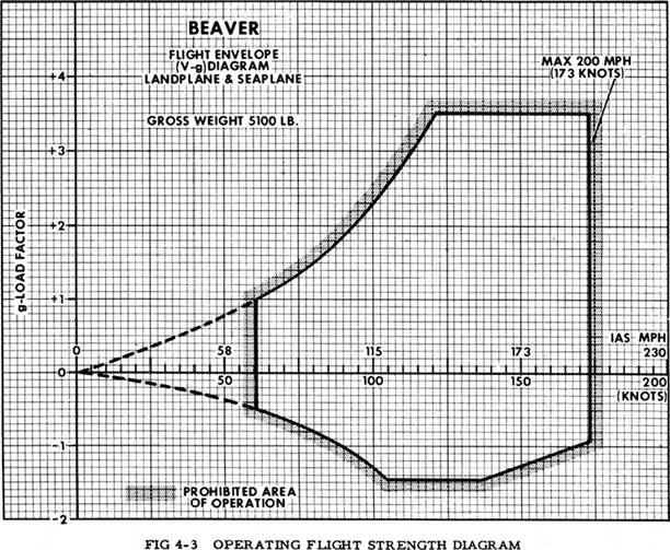
Diving 5, 100 A.U.W. mph (kmh) 180 (290)
Structural
| 840 (4.3) 740 (3.8) 795 (4) 685(3.5) 530 (2.7) 410 (2.1) 405 (652) |
| 655 (1053) |
| 3.52 hrs, 5.68 hrs, |
| 105 (169) 180 (290) 145 (233) |
Cruising 5, 100 A.U. W .mph (kmh) 145 (233)
4.11 FLIGHT CHARACTERISTICS
4.11.1 GENERAL
Stability is good about all axes. The aircraft is easy to fly and is docile down to the stall. Controls are normally effective throughout the airspeed range. The aircraft can be trimmed to fly hands-off from climb to maximum speeds.
4.11.2 TAKE-OFF
When trimmed appropriate to CG position, stick forces are moderate. Weight and Balance must be carefully checked, especially when CG is at, or near, the forward limit. The aircraft will fly itself off at airspeeds of 50 to 60 mph IAS in a tail low attitude.
4.11.3 SLOW FLYING
It is possible to retain full control of the aircraft at;-
75 mph IAS with flaps at CRUISE
65 mph IAS with flaps at LANDING
4.11.4 SPINS
Intentional spinning of the aircraft is prohibited.
4.11.5 STALL
The stall is gentle at all normal conditions of load and flap and may be anticipated by a slight vibration, which increases as flap is Lowered. The aircraft will pitch if no yaw is present. If yaw is permitted, the aircraft has a tendency to roll. Prompt corrective action must be initiated to prevent the roll from developing.
4.12 WING LOAD LIMITATIONS ON
LANDING
On aircraft equipped with either wing-tip tanks, or wing-tip tanks and external wing racks, the maximum permissible load combinations on landing for each wing for the various aircraft configurations are as follows:
| WING-TIP TANKS | * WITHOUT MOD 2/1381 INCORPORATED EXTERNAL STORES | * WITH MOD. 2/1381 INCORP. (Eng. Bulletin "B" No. 10) EXTERNAL STORES | |||||
| 0 lb | 250 lb | 500 lb | 0 lb | 250 lb | 500 lb | ||
| WHEEL | 0 Fuel | Yes | Yes | Yes | Yes | Yes | Yes |
| OR | Half Fuel | Yes | Yes | Yes | Yes | Yes | Yes |
| SKI | Full Fuel | No | No | No | Yes | Yes | Yes |
| 0 Fuel | Yes | Yes | Yes | Yes | Yes | Y es | |
| FLOAT | Half Fuel | Yes | No | No | Yes | Yes | No |
| Full Fuel | No | No | No | Yes | No | No |
* Mod 2/1381 (Engineering Bulletin "B" No. 10) revises the rivet pitch on the bottom skin of the wing.
15 May 1959
Section

|
GENERAL OPERATING- INSTRUCTIONS AND ALL WEATHER OPERATIONS
SECTION V
GENERAL OPERATING INSTRUCTIONS AND ALL WEATHER OPERATION
5.1 ENGINE
5.1.1 MAXIMUM ENGINE EFFICIENCY FOR CRUISING
Maximum engine efficiency and, as a rule, maximum propeller efficiency in cruising is generally obtained when power is reduced by:
(a) Keeping the manifold pressure up to the maximum permitted for cruising at critical altitude.
(b) Reducing the engine speed with the propeller lever until the desired lower airspeed is obtained.
Operation at low engine speed reduces engine losses due to the higher internal friction and horsepower consumption by the supercharger at higher engine speeds.
Cruising at low rpm and high boost gives maximum fuel economy if combined with proper mixture leaning.
On reaching the Lowest usable rpm, use the throttle lever to keep the manifold preesure below the maximum allowable for cruising, or at the desired pressure.
Above the full throttle altitude, constant power can be maintained by increasing the engine speed approximately 75 rpm for each inch Hg. loss in manifold pressure.
Conversely, in descending, a gain of one inch Hg. in manifold pressure can be cancelled in its effect on engine power by decreasing the engine speed by approximately 75 rpm.
NOTE
When cruising at sustained low rpm with low boo 8t, it is advisable to clear
the engine at least once an hour by increasing power to rated or maximum continuous power . Engine clearing should be carried out before entering the landing circuit at the conclusion of a flight. This procedure will minimize plug fouling and ensure full power is available when required.
NOTE
Engine speeds below 1,500 rpm are undesirable as the generator may cut out.
5.1.2 DETONATION AND BACKFIRING
In engine operation the following sequence should always be remembered:
(a) Whenever increasing power, first advance propeller lever, then throttle lever.
(b) To decrease power, first retard throttle lever, then propeller lever.
By following this procedure, most occurrences of detonation in engine operation can be avoided. Serious detonation may be caused if the engine is run continuously on one magneto, with manifold pressures as high as 25 to 30 In.Hg.
The main cause of backfiring is throttle pumping during starting operation. Once the engine has started and reached, through positioning of the throttle lever, an engine speed of 500 to 600 rpm, the throttle lever should be left alone .Throttle pumping at engine speeds above 500 rpm is the frequent cause of backfiring when the engine is cold.
5.1.3 COOLING AND OVERHEATING
While the aircraft is on the ground, continuous running of the engine at high rpm will produce excessive temperatures in engine accessories and should,therefore,be avoided.
NOTE
To insure that the maximum cylinder temperaturee are not exceeded during the take-off, make sure, especially in hot weather, that cylinder head temperatures prior to take-off are well below the maximum for ground tests 450°F (232°C).
Before leaning the mixture after each climb, it is important to give the engine time to cool down, preferably to temperatures below cruising temperatures. A well cooled engine will have less tendency towards detonation when leaning the mixture, than will an engine where the cylinder temperatures are already at the maximum permissible value for cruising.
A tendency towards overheating, noticeable in the increase of both oil and cylinder temperatures, can be checked by:
(a) Reducing engine speed with the propeller lever, rather than by throttling alone and by:
(b) (During climbs) Climbing at an indicated air speed higher than the speed given for best climb.
5.1.4 ENGINE PRIMING
Engine priming requires some experience to obtain good starting under various conditions. Excessive priming will load the cylinders with raw gasoline and has a tendency to wash the oil off the cylinder walls.
NOTE
After unsucce 8 eful attempts have been made to start the engine, the cylinder walls must be recoated with oil by turning the propeller through 3 revolutions with the fuel selector OFF. The piston rings and cylinder walls, thus coated, will not rust if left for one or two day e.
5.1.5 MIXTURE CONTROL
Efficient engine operation depends on careful control of the fuel/air mixture and maintenance of carburettor mixture temperature at 40°F (4°C) at all times except take-off.
With the mixture lever in the RICH position, the fuel supplied is not completely burned. The unburned fuel acts as an internal coolant to prevent detonation. AUTO RICH position should, therefore, only be used for starting, take-off, climb, and when power in excess of that obtainable at maximum lean mixture position is required.
To obtain economical fuel consumption for cruising operation, the carburettor is equipped with an automatic mixture control to provide for mixture leaning at the proper fuel/ air ratios for all altitudes.
When operating in the lean mixture range, constant checks of all temperatures are necessary.
5.1.6 ENGINE ICING
Engine icing occurs in two forms: impact icing and carburettor icing. The ее phenomena may be experienced either individually, or in combination with each other, between free air temperatures of 5°F and 78°F (-15°C and 25°C).
(i) Impact Icing
Under certain conditions, particularly when descending through clouds, snow or heavy rain, impact ice from super-cooled water droplets freezing on metal surfaces will form in the vicinity of the air intake.The gradual blocking of the air intake causes rough engine running, a drop in manifold pressure and finally, as the intake blockage becomes complete, an engine stop.This is nearly always accompanied by severe airframe icing.
(ii) Carburettor Icing
Formation of ice in the carburettor is of two kinds; throttle icing and evaporation ice.
(iii) Throttle Icing
The local increase in the velocity of the air flow at the throttle valve and the choke venturi causes a drop in pressure and temperature which leads, under certain atmospheric conditions, to the formation of throttle ice.
Since each grain of ice constricts the air flow and lowers the temperatvire still further, throttle ice builds up more and more rapidly.
(iv) Evaporation Ice
The temperature of the fuel/air mixture is also reduced by fuel evaporation taking place when fuel is drawn into the carburettor air stream. The heat required for evaporation is taken from the surrounding air and metal. The mixture temperature drop so caused by evaporation alone may be as much as 25°C. Ice, therefore, may be formed in the carburettor even when the outside air temperature is well above the freezing point.
The boost reading will drop immediately as soon as ice accretion in the carburettor starts. This is sometimes accompanied by a slight flickering of both the manifold pressure and tachometer needles.
NOTE
It requires much more heat to melt ice already formed in a carburettor than to prevent its formation.
For best engine operation, the temperature of the carburettor air mixture should be maintained at 40°to 45UF(4° to 7°C) under all circumstances.
NOTE
Engine operation at more than 45°F 7°C)carburettor mixture temperature causes a loss of engine power due to the reduced weight of the cylinder charge.
(v) Carburettor mixture heat should, therefore, be_used at all times with automatic selections. When manual mixture control is used carburettor mixture heat should be used whenever there is the slightest possibility of the occurrence of carburettor icing.
Under these conditions it is a good practice to apply carburettor heat for one or two minutes every half hour during flight in order to preclude the possibility of icing.
Carburettor icing is likely to be encountered at free air temperatures of 20°F to 60°F (-7° to 16°C).
(a) Adjust carburettor heat to keep clear of the icing danger zone,which extends between carburettor mixture temperatures of 28°F and 36°F (-2°C and 4°C).
(vi) Carburettor heat should further be used:
(a) When rough engine operation occurs in cold, clear air with low cylinder head and carburettor air temperature8.
Increase carburettor heat only enough to eliminate engine roughness.
(b) When the fuel/air mixture may be too cold for proper vaporization and fuel economy during low power cruising.
| 5.2 |
| 5.2.1 |
Use carburettor heat as necessary to obtain smooth engine operation and to eliminate plug fouling.
OIL DILUTION
GENERAL
For starting in cold weather, the engine oil may be diluted by adding fuel.
The amount of fuel to be added to the engine oil depends on the air temperature anticipated at the time of the next start. Recommended dilution percentages' and dilution times for various temperatures are given in the table below. To achieve the recommended
Max. Oil Tank Contents before starting Dilution
|
| Dilution % by Vol. |
| Anticipated Air Temp. At Next Start |
| Dilution Time at 1000 RPM |
percentages, the dilution switch is to be held "ON" for the time of the dilution run.
5.2.2 RE DILUTION
If a short ground-run is made with an engine which has previously been prepared for cold weather starting, it is necessary to redilute the engine oil before shutting down. To arrive at the correct time for rediiution proceed as follows:
(a) Divide ground-run time in minutes by 60.
(b) Multiply the time in the Dil. Table by the fraction found through step (a).
Example: Ground-run time is 15 minutes. Dilution percentage requires 20%.Normal dilution time given in Dilution Table: 3 minutes.
(a) 15/60 . 1/4 (b) 3x1/4. 3/4 minute. NOTE
In extreme cold weather only a negligible amount of fuel is "boiled off" during a short ground-run. Under these conditions there may be no need for rediiution of the engine oil.
5.2.3 OIL TANK LEVELS
During the dilution run, approximately 1 gallon of fuel is added to the engine oil in 4 to 5 minutes. Thus, additional volume is required in the oil tank and may have to be provided by draining the oil tank down to the maximum permissible level before oil dilution is started. On the other hand, the addition of fuel causes the oil level to rise above the filler inlet level.
The oil tank filler cap should not be removed when an aircraft has been prepared for cold weather starting.
5.2.4 OIL DILUTION PROCEDURE
To insure that recommended oil dilution pcrccntagcs are obtained proceed as follows:
(a) Allow oil temperature to drop to between 85°F and 100°F (30°C to 40°C) during shutdown run of engine.
(If an oil temperature of less than 125°F (50°C) cannot be obtained with the engine running, the engine should be shut-off until the oil has cooled to below 100°F (40°C).
(b) Select the dilution percentage required from the Oil Dilution Table and corresponding maximum permissible tank contents.
(c) Make sure oil level in the tank is down to permissible maximum.Stup the engine to have oil drained or added, if necessary.
(d) Propeller lever at DECREASE RPM.
(e) Throttle lever to give 1000 RPM.
(f) Hold oil dilution switch ON for the recommended dilution time.
(g) Move propeller lever several times to INCREASE RPM during the last two minutes of the dilution run to inject diluted oil into the propeller cylinder and governor pipelines.
(h) When the oil dilution period has elapsed, hold dilution switch in the ON position until the engine has stopped. Stop the engine with propeller in the DECREASE RPM position and mixture lever at IDLE CUT-OFF.
The diluted oil tends to loosen carbon and sludge deposits within the engine. The oil screen should therefore be removed and cleaned immediately after the first use of the dilution system each season, and inspected daily until carbon collection on the screen returns to normal. Thereafter the usual screen inspection will be adequate. The oil pressure should be watched closely for indications of oil screen clogging.
NOTE
Oil dilution should not be used intermittently during the season but continued once it has been star ted. Otherwise, oil screen cleaning, as recommended above, must be repeated.
The fuel content in a diluted engine oil system is "boiled-off" within 3/4 to one hour at normal operating temperatures. High oil inlet temperatures of 160°F (70°C) and above will shorten fuel evaporation time.
When preparing for a long flight, it should be borne in mind that dilution decreases the amount of oil available for engine lubrication, depending on the engine condition and the extent of dilution. The pilot will have to rely upon experience in arriving at safe limits for each particular flight.
5.3 INSTRUMENT FLIGHTS
Before undertaking any instrument
flight:
(a) Ensure proper operation of all flight instruments .
(b) Checknavigation and communication equipment.
(c) Check pitot heater and carburettor heat.
(d) (Night flying)Check panel lights,navigation lights and landing light.
5.3.1 FLIGHT IN TURBULENCE AND THUNDER STORMS
(a) Attain manoeuvering speed as given in Section IV and maintain a steady flight attitude without changing air speed and rate of climb indications .
(b) Flight in thunderstorms should be avoided if possible.
5.4 OPERATION IN SUB-ARCTIC CLIMATES
5.4.1 METEOROLOGICAL PHENOMENA
Meteorological phenomena peculiar to cold weather are:
Ice crystals result from the sublimation of water vapour and are a form of precipitation. Their concentration is never heavy, so that the horizontal visibility seldom falls below 5 miles.
Prevailing ice crystals, however, can rapidly produce the much more dangerous ice fog by the mere operation of an aircraft engine. When landing at an airfield reporting ice crystals, it is recommended:
(a) To do a minimum of low flying.
(b) To come in on a straight approach.
Ice fog is a heavy concentration of ice particles forming on nuclei in the air. It is most prevalent in industrial areas but can be caused, at very low temperatures, by the running of an engine.
The propeller wash and combustion products from an aircraft engine can provide the disturbance and nuclei, under certain atmospheric conditions, to fog an aerodrome to a height of approximately 50 feet.
Horizontal visibility may then be down to a few hundred feet, while downward visibility is generally adequate.
At night, glare will be reduced, if landing and navigation lights are left "OFF".
Thin mist may often occur in the sub-arctic when the sun does not dissipate fog and low clouds*
Vertical visibility remaining good, the horizontal visibility is poor.The formation of ice and frcst should always be anticipated under these conditions.
Blowing snow may obscure the landing strip and make a safe landing doubtful. Landing lights should be left "OFF" in blowing snow during night landing.
5.4.2 EFFECT ON AIRCRAFT AND EQUIPMENT
Low temperatures adversely affect aircraft and equipment, fuel and oil as follows:
Plastics become brittle and may crack when the aircraft is moved from a warm hangar to an outside dispersal point.
(a) Look for small cracks at edges of mounting frames or at small radii on curved panels.
(b) Check cockpit windshield carefully as cracks may lead to its disintegration in flight.
(c) Handle doors with caution.
Synthetic Rubber of certain types used in flexible oil and fuel lines and for coating electrical cables may 1озе flexibility.
(a) Avoid bending to prevent cracking of material.
Control cable8 tensioned ineide a hangar become slack as the airframe contracts more than the steel cables, with a given temperature drop.
Batteries lose as much as 50% of their charge at 0° (-18°C) and cannot be charged at normal rate.
(a) Leave only fully charged batteries outside. They will not freeze, but their usefulness is very limited.
(b) If forecast temperature is below -22°F (-30°C), keep battery in a warm place to ensure use when required.
NOTE
If batteries are not fully charged and left outside there is danger of freezing of the electrolyte and splitting of the battery case.
Tires on dispersed aircraft may stiffen with a flat spot frozen on them.
(a) Taxi aircraft and flat spot will disappear.
Hydraulic and pneumatic leaks may appear more frequently.
(a) Decide whether corrective action shojild be taken as small leaks or seepage will usually disappear with increasing temperatures.
Snow and frost can be brushed off the exterior of aircraft without difficulty.
(a) Always remove snow from aircraft when a thaw is forecast in order to prevent later freezing.
Ice may require heat for its removal, making it necessary to:
(a) Fit covers on aircraft removed from a warm hangar during precipitation.
(b) Fit blanking plates to air intakes after shutting down.
(c) Watch for ice, in the vicinity of fuel tank vents, caused by condensation.
(d) Remove ice or snow from the inside of the propeller spinner as resulting unbalance may cause dangerous vibration.
High static charges can develop during removal of snow or ice. As the fuel/air mixture which is produced when gasoline evaporates at temperatures from 14°F (-10°C) to -40°F (-40°C)is explosive, refueling presents a much greater fire hazard in very cold weather.
It is therefore recommended:
(a) Ground aircraft electrically, as well as possible.
(b) Wait for 30 minutes for electric charge on rubber and plastic parts to leak off.
(c) Make sure that charges built up in the body of refueling crew «Ire discharged by having them touch metal surface with bare hands. (Wipe moist hands dry if necessary as moist skin will stick to the metal instantly).
Fuel in drums from a cache necessitates precautions as under:
(a) Always filter fuel from drums.
(b) Do not use fuel from a drum which has been partly used, as the remaining fuel may be contaminated.
NOTE
The octane value of cached fuel may be lower than marked, as fuel slowly deteriorates in storage.
Short Engine runs. Engines should be run only to be brought up to operating temperature. If run only for a short period, water vapour in combustion products escaping past the piston will condense inside the crankcase and be distributed throughout the oil system. Split oil coolers, choked oil lines and possible engine failure may be the result.
(a) Avoid short engine ground runs.
5.4.3 PRE FLIGHT CHECKS
In addition to checks called for in paragraph 2.1.8 of Section II, the following checks must be carried out before starting the engine.
(a) Inspect hydraulic brake lines for cracks, breaks or leaks.
(b) Fuel tank vents free from ice.
(c) Snow, ice or hoar frost removed from wings and tailplane •
(d) Hinges of all control surfaces free from particles of ice or hard snow liable to cause jamming.
(e) Test all main and auxiliary controls to ensure they have not become stiff or blocked with ice and snow.
(f) Defrost windows, as necessary but do not scrape off.Use alcohol to remove light film of frost forming during warm-up.
(g) Keep window open during run-up to prevent misting of windshield.
(h) Check cold weather emergency equipment for completeness and proper stowage.
(j) Position engine winter shutters(if installed) to suit temperature conditions.
5.4.4 ENGINE STARTING
If time and equipment are available, engine and accessories should be preheated. Cold starting, if necessary during very cold weather, will be easier if the following action is taken:
(a) Keep batteries and battery cart warm, indoors, until just before they are required.
(b) Apply heat to the engine if it is not possible to pull the engine through by using the starter (starter clutch slipping).
(c) For priming use normal fuel down to outside air temperatures of -13°F (-25°C). Preheat engine below this temperature.
WARNING
As a large amount of priming is necessary, cold starting creates an additional fire hazard resulting from excess fuel which might flow from engine drains.
(d) If first attempt to cold start fails, allow 5 or 10 minutes before making another attempt so that the heat generated during the false start can vaporize priming fuel which may have made spark plugs wet.
(e) Apply heat to the oil pressure line if oil pressure does not begin to show within 30 seconds, and congealed oil in the line to the pressure gauge is suspected as the cause of the trouble.
(f) Heat oil feed line if zero oil pressure is indicated and a clogged feed line is suspected of stopping the oil flow from the tank (there is a possibility that undiluted oil from the tank body has flowed into the feed line to the oil pump after the oil system has been diluted).
(g) Exercise great care in operating electric starters at low temperatures.
(h) Check suction indicator to make sure that drive shaft has not sheared off during a cold start.
When using external heat, it should be directed onto the cylinders, accessories, oil feed line and oil cooler. The amount of heat required will depend upon the air temperature, wind velocity, oil dilution percentage and whether engine covers are being used.
5.4.5 WARMING UP
To aid smooth running during warm
up:
(a) Use carburettor heat and/or protected air.
(b) Adjust engine winter shutters to maintain cylinder heat temperatures within operating limits.
(c) If engine tends to fade out, operate primer pump intermittently.
(d) Maintain suitable engine speed until minimum oil temperature is reached.
(e) Watch for oil foam seeping through the crankcase breather, and stop spewing by reducing power.
5.4.6 TAXIING
During taxiing the following precautions should be observed.
(a) Do not stop aircraft on slush, continue moving until dry snow or ice is reached,
(b) Look out for obstacles, after a recent snowfall covering air field markers,
(c) Taxi slowly in icy conditions.To bring high idling rpm down, try low rpm setting and carburettor heat to reduce power(in extreme cold, however, the use of carburettor heat results in a power increase). Adjust engine winter shutters (if installed).
(d) Ensure engine is warm on reaching takeoff position as taxiing will allow the engine and carburettor to cool.
(e) Switch on pitot heat when taxiing to ensure that the pitot is warm before taking off.
5.4.7 TAKE-OFF
Some of the precautions to be observed when taking off are:
(a) At ambient temperatures below standard altitude temperature (15eC (59eF) at S.L.), maximum permissible take-off MAP is reduced by 2% per lleC (20°F) below standard. See Figure 4-1.
(b) Carry out a precautionary type of take-off from unpacked snow or slush as the rate of acceleration is poor under these circumstances.
(c) Expect sudden frosting of windshield during a climb from the field in an inversion.
(d) Open engine winter shutters to maintain cylinder head temperature within limits.
WARNING
Do not attempt to take-off with snow, ice or frost on the wings.
5.4.8 CRUISE
During flights in very cold weather the following precautions should be observed:
| SO |
(a) Expect vacuum operated flight instrument (directional gyro,turn and bank indicator, artificial horizon) to be unreliable because of bearing friction caused by congealed lubricants.
(b) Operate flaps several times to prevent freezing in the "CRUISE" position.
(c) Above 60° to 65°N. latitude expect magnetic compass to be generally unreliable, so steer by gyro only.
(d) Operate propeller lever(every 30 minutes) to give 300 rpm decrease from cruise rpm and return to cruise rpm.
(e) Adjust engine winter shutters (if installed) to maintain engine and oil temperatures within operating limitations.
5.4.9 LANDING
When landing under cold and extreme cold weather conditions observe precautions as follows:
(a) Approach and land at higher speeds as the stalling speed is increased when there is ice on the aircraft.
(b) Judge height by reference to trees, fences, other aircraft or hangars when landing on clean snow.
(c) Apply brakes earlier than normal, depending on conditions.
NOTE
| Revised 31 Jan 1961 |
Maintain engine temperatures during descent to avert engine failure or choking in the event of a baulked landing.
5.4.10 AFTER LANDING
(a) Fill fuel tanks as soon as possible after landing to prevent condensation.
(b) Do not leave parking brakes on as they may freeze in this position, if moisture is present.
(c) Leave throttle lever partially open after shutting down :o permit starting, if the engine controls become too stiff, and to prevent freezing of the butterfly valve.
(d) Have all covers fitted immediately if the aircraft is to be dispersed; blowing snow will enter any opening.
5.5 OPERATING IN TROPICAL
CLIMATES
Aircraft operated under tropical conditions require protection from heat and humidity .Sand and dust filters may be necessary for operation in desert areas.
Heat affects components in various ways. Fuel in tanks tends to expand and vaporize. Flight control cables should be watched for tension as the material used in the construction of the aircraft will expand farther than the steel cables, thus tightening them.
Always shade aircraft if possible, including wing tip tanks if fitted.Cover plastic materials only, if necessary, for sand protection.
Close fitting covers are undesirable as they increase the temperatjire and may cause permanent deformation ofPlexiglas panels.
5.5.1 STARTING AND TAXIING
(a) Check tire pressures.
(b) Drain moisture from fuel tanks and fuel system.
(c) Underprime first in starting.Increase amount of priming as required.
(d) Keep warming-up time to a minimum.
(e) Avoid long taxiing rune and delayed take- offs to keep cylinder head and oil temperatures below their maximums. (Use tractors for aircraft dieper sal).
(f) Avoid unnecessary braking as brake drums overheat quickly.
5.5.2 TAKE-OFF
In tropical climates take-off dis- stances will be longer because the air is less dense.
5.5.3 CLIMB
In hot weather generally:
(a) Allow a greater distance to clear obstacles.
Satisfactory cooling is provided for operation in a standard atmosphere with a ground temperature of 100°F (40°C). If this temperature is exceeded it may become necessary to climb the aircraft at airspeeds higher than those quoted in Section II.
5.5.4 CRUISE
To avoid over-heating during flight under extreme conditions it may be necessary:
(a) To operate in "rich" mixture and/or with increased power.
(b) To confine low flying to take-offs and landings.
Under extremely hot conditions the pilot should:
(a) Expect greater landing distances as the true airspeed will be higher than the indicated airspeed.
(b) Uее ground objects for judgement of height because rising heat may produce a false horizon due to mirage effect.
5.5.5 AFTER LANDING
(a) Refuel at the coolest time of the 24 hour period.
(b) Keep fuel tanks filled in order to reduce condensation to a minimum.
(c) Apply parking brakes only after brake drums have cooled.
(d) Leave windows slightly open to induce air circulation in the cabin.
Section
| z о u Ш со |

|
orbUIAL-^
INSTALLATIONS
SECTION VI SPECIAL INSTALLATIONS
COMBINATION WHEEL-SKI INSTALLATION
6.1 The de Havilland combination wheel-
ski installation permits normal operation on wheels or skis at the discretion of the pilot. It is possible to taxi immediately from snow covered ground onto cleared runways or dispersal areas and vice versa since the skis can be raised or lowered while the aircraft is being taxied. Partial retraction of the skis facilitates the use of wheel brakes, for ground manoeuv- ering.
6.1.1 GENERAL
The skis are raised or lowered in relation to the wheels by means of a hydraulic control unit located on the cockpit floor to the right of the pilot's seat. The skis are raised by selecting UP on the selector lever then operating the hydraulic hand pump which supplies hydraulic pressure to extend an actuator and cause the ski linkage to swivel on the axle attachments. The hydraulic pressure works in opposition to a compressed air charge, in the upper portion of the actuator housing, which is used as a pneumatic spring to cushion the landing impact.
To lower the skis, select DOWN on the selector lever which will release the hydraulic pressure and allow the pneumatic pressure in the upper portion of the actuator housing, to return the skis to the DOWN position as shown on the indicator in the selector unit.
6.1.2 OPERATION
To lower skis select DOWN on the ski selector lever.After a few seconds the indicator will show that the skis are in the DOWN position.
To raise the skis select UP on the ski selector lever. Operate the hand pump until the skis are fully UP as shown by the needle on the indicator. Approximately 100 strokes of the handpumpare required to raise the skis fully.
NOTE
The skis trim safely in flight at any degree of retraction. Therefore, the pumping may be completed at the pilot's convenience, and in stages if desired.
6.1.3 TAXIING
Manoeuvering on snow can often be assisted through partial retraction of the skis as follows:
(a) Select UP on the ski selector lever and retract skis by operating the handpump until the brakes become effective.
(b) On firm ground skis should be retracted fully to avoid accidental damage of the skis by unobserved rough ground.
(c) On cleared runways, taxiing strips and dispersal aprons, satisfactory taxiing may be carried out with the skis two thirds retracted if it is desired to avoid complete retraction.
6.1.4 AFTER TAKE-OFF
The ski position has no significant effect on airspeed, CG position or flight characteristics. The skis, therefore, may be left in either UP or DOWN position as dictated by conditions at the arrival landing field.
6.1.5 BEFORE LANDING
Prior to the approach to land the pilot should decide whether to raise or lower the skis, depending on the forecast conditions of the landing field. Select skis as desired and when the actionis complete check the ski position visually and on the indicator.

Г
| ACTUATOR |
| LINKAGE UNIT |
RESTRAINING GEAR
TRIM UNIT
FIG 6-1 COMBINATION WHEEL-SKI INSTALLATION
6.1.6 LANDING
Make a normal approach at the speeds recommended in Section 2.13.
A tail-down or three point landing attitude should be attained on the final stage of the approach to reduce the landing run, and, when skis are extended, to ensure that raised lumps of snow or ice do not foul the ski tips on touchdown.
6.1.7 CROSS WEND LANDINGS
When landing with skis extended the crosswind component should be carefully considered against the pilot's experience and the condition of the landing area at that time. Landings with crosswind components equal to 12 mph at 90° are not recommended.
6.1.8 AFTER LANDING
As soon as possible, after touchdown, ease the control column fully back to ensure directional control via the rudder pedals and tailwheel or tail ski and proceed as in Section 2.16.
6.1.9 ON GROUND
If the tires freeze to the ground, lower the skis to free them.If the skis "freeze in"retract the skis to break free from the ice.
6.1.10 PRE FLIGHT CHECKS
When the aircraft has been parked with the skis UP check that the running surfaces of the skis are free of ice which may have formed by re-freezing of melted snow or slush sprayed up while taxiing on wheels. Heavy frost conditions will sometimes encrust the running surfaces of the skis.
If the main ski running surfaces are left unclean a subsequent ski landing may result in an abrupt stop or, if one ski only is encrusted, a ground loop. Visually check in
flation of actuator. Under normal operating conditions at full load, with skis down, 1 to 1.5 inches of the actuator shaft should be exposed.
NOTE
Actuator pressure changes of 60 to 70 psi due to temperature variations, etc., have only a minor effect on ski operations and do not require compensation.
6.2 AMPHIBIOUS FLOATS
The de Havilland amphibious floats installation enables routine flights to be made, from airfield to airfield, water to water, airfield to water and water to air field conveniently and simply without delays in re-equipping the aircraft.
6.2.1 GENERAL
The floats installation replaces the complete landplane landing gear system. The floats are equipped with retractable water rudders,main and nose wheels.The retraction and extension of the wheels is accomplished by means of hydraulic pressure emanating from a hydraulic control unit, located on the floor to the right of the pilot's seat.The main wheel braking system is also operated hydraulically through actuation of the rudder toe pedals.The water rudder s are actuated through a cable and pulley system for retraction, extension and steering.
6.2.2 OPERATION
Before Flight Inspection
On Land
Check the contents of the starboard hydraulic tank then, starting at the nose of the starboard float, check the following:
(a) Wheel chocks in position.
(b) Nosewheel tire pressure 30 psi, creepage and general condition.
(c) Shock strut extension.
(d) General condition of nose bumper and nose- wheel retraction cable.
(e) Condition of float planing surfaces.
(f) Condition of mainwheel well, inspect hydraulic actuation and brake pipe lines, for condition and leakage.
(g) Mainwheel tire pressure 45 psi, creepage and general condition.
(h) Water rudder retraction and actuation cables for security and condition.
(j) Water rudder for retracted position and general condition.
(k) Repeat checks in the reverse order on the port float.
(1) General condition and security of spreader bars, water rudder cables and pulleys, electrical and hydraulic connections on the floats and entry points into fuselage.
Before Flight Inspection
On Water
Repeat checks as above omitting a,
e, and f.
6.2.3 ON ENTERING THE AIRCRAFT
In addition to the normal airplane
checks:
(a) Observe selected position of the wheels on the amphibious floats hydraulic control unit, loeated on the cockpit floor to the right of the pilot's seat, also the position of the water rudders retraction handle, on the floor to the left of the pilot's heel.
(b) Ensure that theU/C WARN circuit breaker switch, on the right hand electrical panel, is selected ON (Red diagonal lines show on indicator when circuit is broken).
6.2.4 TAXIING Seaplane
Ensure that the wheels are retracted (UP) then cast off the mooring rope.Extend the water rudders and proceed to take-off point. Allow the seaplane to weathercock into the wind and complete engine checks, if not already done. Retract water rudders and take-off into
|

|
FIG 6-3 AMPHIBIOUS FLOATS INSTALLATION
the wind.The water rudders may be left extended to assist in crosswind take-offs.
Landplane
In addition to the checks in Section 2, para. 7, make sure that the wheels are selected DOWN and check that the indication on the hydraulic control unit indicator is a wheel. Before commencing taxiing, check that the water rudders retraction handle is in the retracted position. Test the brakes as soon as the aircraft starts moving.
NOTE
Although the aircraft is in a tricycle undercarriage attitude giving better taxiing visibility more care should be taken to avoid rough or uneven ground in order to avoid damage to the floats. Furthermore, when manoeuvering, the pilot must keep in mind the additional area required for the length of the floats.
6.2.5 TAKE-OFF Landplane
In addition to the checks in Section 2.9 check the following:
(a) Wheels DOWN - Wheel indication.
(b) Water rudders - Retracted.
(c) Brakes - OFF.
(d) Open throttle slowly to take-off power and note that the aircraft accelerates more rapidly, because of the tricycle attitude. Maintain directional control by coarse use of the rudder initially.
(e) Allow the speed to increase to 60 or 65 mph before applying a slight backward pressure to the control column to assist the airplane in unsticking.
(f) As the nose wheels lift clear of the ground a slight forward pressure should be applied to the control column to maintain the take-off attitude.
Seaplane
Complete the normal checks in Section 2.9 with the addition of the following:
(a) Wheels up - UP.
(b) Water rudders - Retracted.
(c) Open throttle smoothly and maintain direction with the airplane rudder. Allow the seaplane to fly itself off at approximately 65 mph.
6.2.6 CLIMBING, CRUISING AND DESCENDING
In flight whether climbing, cruising or descending, the effects of the amphibious floats are the same as those encountered with normal floats. However, to improve the flight characteristics, the wheels should be retracted during flight.The water rudders should be retracted during take-off and remain retracted until after a water landing has been completed.
6.2.7 LANDING
Before approaching to land at the termination of the flight, the pilot must consider his intended landing area and take action accordingly.
If the landing is to be made:
(a) On water, the wheels and water rudders must be retracted (UP).
(b) On land, the wheels must be selected DOWN and locked and the water rudders retracted.
The water rudders retraction is simply a matter of checking that the retraction handle on the floor to the left of the pilot's left heel, is in the retracted position where it should have been before take-off and during the flight.
The wheels, however, require that:
(a) The selector lever on the amphibious floats hydraulic control unit be selected as desired.
(b) The handpump is operated until the desired position UP or WHEEL, is shown on the hydraulic control indicator.
NOTE
Press in the quadrant engaging arm on the selector lever to release the catch from the quadrant before moving the selector lever from the forward UP position to the rear DOWN position or vice versa and ensuring that the catch re-engages with the quadrant at the completion of the selection. It should be noted that with the selector lever in the DOWN position an extension on the lower part of the selector lever engages a protruding solenoid plunger, which prevents the wheels from being selected up when the weight of the aircraft is on the wheels.
When the aircraft weight is not on the wheels a switch on the main gear retracts the solenoid plunger allowing the lever to be selected up. If, when airborne, the plunger does not retract and it is desired to operate the gear, the plunger can be depressed manually.
6.2.8 OPERATING LIMITS
The All-Up Weight of the amphibian (with amphibious gear Part No. C2-UF-2455) when operating on water must not exceed 5000 lb, this reduction in A.U.W. from the standard seaplane version is necessary due to the decreased buoyancy of the amphibious floats. Refer to paragraph 6.3.12 for the allowable increase in A.U.W. of the amphibian when using water- dropping tanks.
NOTE
Handling and performance are unchanged, except as stated below.
Handling
On wheels, if take-off is attempted at the minimum speed 58-60 mph IAS, the nose, once lifted will tend to rise and must be checked. This is a normal nose wheel airplane characteristic and is easily controlled by elevator. If the nose is left down until 80 mph IAS, this characteristic is absent.
Performance
There is negligible difference between the wheels up and down performance.
Runway take-off - Add 50 feet to landplane figure (Chart I).
Runway landing - Add 95 feet to landplane figure (Chart II).
Rate of climb - Subtract 50 fpm from seaplane values (Para. 4.10.1). 58
Speed at maximum weak mixture power (300 ВНР) - Subtract 2-1/2 mph from seaplane (Para. 4.10.1).
Speed al standard cruise (240 ВНР) - Subtract 5 mph from seaplane (Para. 4.10.1).
6.3 WATER-DROPPING TANKS (STAND
ARD SEAPLANE AND AMPHIBIAN)
The de Havilland water-dropping tanks installation, fitted to the standard seaplane or amphibian on special order, is used for fire- fighting. The tanks will automatically fill whilst in motion on the water after touchdown or during the take-off run. This permits rapid replenishment for fighting forest fires when time is the important factor and where the length of water run is restricted. At a speed of 40 mph the tanks can be fully refilled in 18 seconds.
6.3.1 GENERAL
The water tanks installation consists of a five feet long, 17 inch diameter, tank mounted on top of each float. Each tank has a capacity of 49.1 Imp. gals with a limit load of 45 gallons each. A filler tube attached by brackets to the inboard side of each float, extends down into the water to a point approximately 3 inches above the keel of the float. The tube discharges into a 7-1/2 inch wide opening along the top of the tank. A graduated scale in each tank is visible to the pilot through the rear view mirror and enables him to check the quantity. A control lever, located centrally beneath the alternate compass position in front of the pilot, is con- ncctcd by means of cables and pulleys to the forward end of each tank. Pulling this control lever towards the pilot disengages a lock and rotates each tank in an inboard direction approximately 130* to empty the contents. The tanks are mass balanced and will return to their normal locked positions when the control lever is released.
6.3.2 OPERATION
6.3.3 Before Flight Inspection
In addition to the checks detailed in Section II, ensure that the water tanks are securely mounted on the floats and that the pulleys and cables are unrestricted in movement. Ensure that the aircraft loading with the water tanks empty is such that, on take-off, the CG limits will not be exceeded as the tanks become full. Ensure that the ventral fin is installed.
1 NOV 1962
6.3.4 On Entering the Aircraft
In addition to the checks detailed in Section II, ensure that the water tanks control lever is pushed fully in and, if necessary, adjust the external rear view mirror on each door so that the tank quantities can be readily seen by the pilot.
6.3.5 Taxiing
Take care during taxiing to avoid weeds so that the tank inlet tube will not become obstructed. During taxiing and engine tests, the water tanks will begin to fill if the speed is above 40 mph. (Refer to paragraph 6.3.12).
6.3.6 Filling and Take-off
Complete the checks detailed in paragraph 6.2.5. During the take-off run, maintain 40 mph until the tanks are filled (45 gal.) then increase power and complete normal take-off. The tanks will fill in approximately 18 seconds.
6.3.7 Climb
Restrict the angle of climb to avoid spilling water from the tanks.
6.3.8 Cruise
When water tanks are installed, the cruising airspeed is approximately 10 mph less than that shown in paragraph 4.10.1 for the seaplane.
6.3.9 Emptying Water Tanks
When emptying the water tanks over a forest fire etc, the direction and speed of the wind has very little effect on the water coverage pattern since the greatest percentage of the water falls very rapidly. Adrift allowance of approximately seven feet for every one mph of wind speed effective at 100 feet altitude has been found satisfactory. This formula applies regardless of the direction of flight since the pattern and density of the falling water is dependent on the altitude of the aircraft at the time of release. High altitude dumping results in a light widespread pattern, whereas low altitude dumping results in a heavy concentrated pattern. The wing flaps should be lowered to CLIMB setting and a steady airspeed of 85 to 90 mph IAS should be maintained at the desired altitude when dropping the water. The dumping of the water should be completed one second before the center of the target is reached. Approximately two seconds are required to empty the
1 NOV 1962
tanks completely. The tanks will return to their normal positions and lock when the control lever is released.
6.3.10 Refilling the Tanks
Refilling the water tanks is accomplished by making a normal seaplane landing using TAKE-OFF flaps setting, maintaining a taxi speed of 40 mph until the tanks are filled (45 gal.) then increasing power to become airborne again.
6.3.11 Handling
At all timee the pilot should consider the aircraft as being fully loaded, observing the normal precautions. To maintain the CG within limits, if loaded CG aft, empty the rear fuel tank first; if loaded CG forward, empty the front fuel tank first. Reduction in A.U.W. can be accomplished by removal of the rear seats or by reducing the fuel load.
NOTE
The Safe Moment Limits must be maintained within the limits shown in paragraph 6.3.13.
6.3.12 WEIGHT LIMITATIONS
1. Standard Seaplane A.U.W. - 50901b This A.U.W. is applicable under all conditions.
2. Amphibian A.U.W. - 5000 lb
This A.U.W. may be increased to a maximum of 5090 lb when the excess weight above 5000 lb is picked up while taxiing (on the step) at a speed in excess of 40 mph.
CAUTION
Should a take-off be aborted after the water dropping tanks are full (at A.U.W. 5090 lb), then the water contents must be jettisoned immediately in order to reduce the A.U.W.
NOTE
Do not taxi or manoeuvre the amphibian on the water at an A.U.W. in excess of 5000 lb.
6.3.13 WEIGHT AND MOMENT TABLE
When equipped with the water tanks
installation, the aircraft basic weight is affected as follows:
| Arm in. |
| Weight lb. |
| Mom |
Add to Basic Aircraft
Water
Дата добавления: 2014-12-23; просмотров: 116; Мы поможем в написании вашей работы!; Нарушение авторских прав |