КАТЕГОРИИ:
АстрономияБиологияГеографияДругие языкиДругоеИнформатикаИсторияКультураЛитератураЛогикаМатематикаМедицинаМеханикаОбразованиеОхрана трудаПедагогикаПолитикаПравоПсихологияРиторикаСоциологияСпортСтроительствоТехнологияФизикаФилософияФинансыХимияЧерчениеЭкологияЭкономикаЭлектроника
APPENDIX F. SUPPLEMENTARY TEXTS
Tesla coil
A Tesla coil is a type of resonant transformer, named after its inventor, Nikola Tesla. Tesla coils consist of two, or sometimes three, coupled resonant electric circuits. Tesla experimented with a large variety of coils and configurations, so it is difficult to describe a specific mode of construction that will meet the wants of those who ask about “Tesla” coils. Tesla used these coils to conduct innovative experiments in electrical lighting, fluorescence, x-rays, high frequency alternating current phenomena, electrotherapy, and wireless power for electric power transmission.
Tesla’s early and later designs usually employed a high voltage power source, one or more high voltage capacitors, and a spark gap to excite the primary side of the Tesla Coil periodic burst of high frequency current. An important characteristic of his later, higher power coil designs was that the primary and secondary circuits were also tuned so that they resonated at the same frequency (typically, but not always, between 25 kHz and 2 MHz).
A Tesla Coil transformer operates in a significantly different fashion than a conventional (i.e., iron core) transformer. In a conventional transformer, the windings are very tightly coupled, and voltage gain is limited to the ratio of the numbers of turns in the windings. However, the voltage gain of a disruptive Tesla Coil can be significantly greater, since it is instead proportional to the square root of the ratio of secondary and primary inductances. The coil transfers energy from one oscillating resonant circuit (the primary) to the other (the secondary) over a number of RF cycles. As the primary energy transfers to the secondary, the secondary’s output voltage increases until all of the available primary energy has been transferred to the secondary (less losses). Even with significant spark gap losses, a well designed Tesla coil can transfer over 85% of the initial energy initially stored in the primary capacitor to the secondary circuit.
Tesla's original design for his largest coil used a top terminal consisting of a metallic frame in the shape of a toroid, covered with smooth half circular metal plates (constituting a very large conducting surface). The top terminal has relatively small capacitance, charged to as high a voltage as practicable. The outer surface of the elevated conductor is where the electrical charge chiefly accumulates. It has a large radius of curvature, or is composed of separate elements which, irrespective of their own radii of curvature, are arranged close to each other so that the outside ideal surface enveloping them has a large radius. This design allowed the terminal to support very high voltages without generating corona or sparks. Tesla during his patent application process described a variety of resonator terminals at the top of this later coil. Most Modern Tesla coils use simple toroids, typically fabricated from spun metal or flexible aluminum ducting, to control the high electrical field near the top of the secondary and to direct spark outward, and away, from the primary and secondary windings. For a variety of technical reasons, toroids provide one of the most effective shapes for the top terminals of Tesla coils.
Larger pulses of displacement current further ionize and heat the air at the point of initial breakdown. This forms a very conductive “root” of hotter plasma, called a leader, that projects outward from the toroid. The plasma within the leader is considerably hotter than a corona discharge, and is considerably more conductive. In fact, it has properties that are similar to an electric arc. The leader tapers and branches into thousands of thinner, cooler, hairlike discharges (called streamers). The streamers look like a bluish “haze” at the ends of the more luminous leaders, and it is the streamers that actually transfer charge between the leaders and toroid to nearby space charge regions. The displacement currents from countless streamers all feed into the leader, helping to keep it hot and electrically conductive.
In a spark gap Tesla Coil the primary-to-secondary energy transfer process happens repetitively at typical pulsing rates of 50-500 times/second, and previously formed leader channels don’t get a chance to fully cool down between pulses. So, on successive pulses, newer discharges can build upon the hot pathways left by their predecessors. This causes incremental growth of the leader from one pulse to the next, lengthening the entire discharge on each successive pulse. Repetitive pulsing causes the discharges to grow until the average energy that’s available from the Tesla Coil during each pulse balances the average energy being lost in the discharges (mostly as heat). At this point, dynamic equilibrium is reached, and the discharges have reached their maximum length for the Tesla Coil’s output power level. The unique combination of a rising high voltage Radio Frequency envelope and repetitive pulsing seem to be ideally suited to creating long, branching discharges that are considerably longer than would be otherwise expected by output voltage considerations alone.
Tesla experimented with many circuit configurations. The Tesla Coil primary winding, spark gap and tank capacitor are connected in series. In each circuit, the AC supply transformer charges the tank capacitor until its voltage is sufficient to break down the spark gap. The gap suddenly fires, allowing the charged tank capacitor to discharge into the primary winding. Once the gap fires, the electrical behavior of either circuit is identical. Experiments have shown that neither circuit offers any marked performance advantage over the other.
Modern day transistor or vacuum tube Tesla coils do not use a spark gap. Instead, the transistors or vacuum tubes provide the switching or amplifying function necessary to generate RF power for the primary circuit. Transistor Tesla coils use the lowest primary operating voltage, typically between 175 to 800 volts. Vacuum tube coils typically operate with plate voltages between 1500 and 6000 volts, while most spark gap coils operate with primary voltages of 6,000 to 25,000 volts.
A large Tesla coil of more modern design often operates at very high peak power levels, up to many megawatts (a million watts). It should therefore be adjusted and operated carefully, not only for efficiency and economy, but also for safety. If, due to improper tuning, the maximum voltage point occurs below the terminal, along the secondary coil, a discharge (spark) may break out and damage or destroy the coil wire, supports, or nearby objects.
The primary coil’s resonant frequency should be tuned to the same value of the secondary coil’s, using low-power oscillations, then increasing the power until the apparatus has been brought under control. Tuning can then be adjusted so as to achieve the longest streamers at a given power level, corresponding to a frequency match between the primary and secondary coil. Capacitive “loading” by the streamers tends to lower the resonant frequency of a Tesla Coil operating under full power.
However, even more than 100 years later after the first use of Tesla Coils, there are many aspects of Tesla Coil discharges and the energy transfer process that are still not completely understood.
Superconductivity
When conductors lose all of their electrical resistance when cooled to super-low temperatures (near absolute zero, about –273° Celsius), it must be understood that superconductivity is not merely an extrapolation of most conductors’ tendency to gradually lose resistance with decreases in temperature; rather, it is a sudden, quantum leap in resistivity from finite to nothing. A superconducting material has absolutely zero electrical resistance, not just some small amount.
Superconductivity was first discovered by H. Kamerlingh Onnes at the University of Leiden, Netherlands in 1911. Just three years earlier, in 1908, Onnes had developed a method of liquefying helium gas, which provided a medium for which to supercool experimental objects to just a few degrees above absolute zero. Deciding to investigate changes in electrical resistance of mercury when cooled to this low of a temperature, he discovered that its resistance dropped to nothing just below the boiling point of helium.
There is some debate over exactly how and why superconducting materials superconduct. One theory holds that electrons group together and travel in pairs (called Cooper pairs) within a superconductor rather than travel independently, and that has something to do with their frictionless flow. Interestingly enough, another phenomenon of super-cold temperatures, superfluidity, happens with certain liquids (especially liquid helium), resulting in frictionless flow of molecules.
Superconductivity promises extraordinary capabilities for electric circuits. If conductor resistance could be eliminated entirely, there would be no power losses or inefficiencies in electric power systems due to stray resistances. Electric motors could be made almost perfectly (100%) efficient. Components such as capacitors and inductors, whose ideal characteristics are normally spoiled by inherent wire resistances, could be made ideal in a practical sense. Already, some practical superconducting conductors, motors, and capacitors have been developed, but their use at this present time is limited due to the practical problems intrinsic to maintaining super-cold temperatures.
The threshold temperature for a superconductor to switch from normal conduction to superconductivity is called the transition temperature. Transition temperatures for “classic” superconductors are in the cryogenic range (near absolute zero), but much progress has been made in developing “high-temperature” superconductors which superconduct at warmer temperatures. One type is a ceramic mixture of yttrium, barium, copper, and oxygen which transitions at a relatively balmy -160° Celsius. Ideally, a superconductor should be able to operate within the range of ambient temperatures, or at least within the range of inexpensive refrigeration equipment.
The critical temperatures for a few common substances are shown here in this table. Temperatures are given in degrees Kelvin, which has the same incremental span as degrees Celsius (an increase or decrease of 1° Kelvin is the same amount of temperature change as 1° Celsius), only offset so that 0° K is absolute zero. This way, we don’t have to deal with a lot of negative figures.
Material Element/Alloy Critical temp, (degrees K)
Aluminum----------- Element------------ 1.20
Cadmium------------ Element------------ 0.56
Lead------------------- Element------------ 7.2
Mercury-------------- Element------------- 4.16
Niobium-------------- Element------------- 8.70
Thorium-------------- Element------------- 1.37
Tin--------------------- Element------------- 3.72
Titanium------------- Element------------- 0.39
Uranium-------------- Element------------ - 1.0
Zinc-------------------- Element------------ - 0.91
Niobium/Tin -------- Alloy ------------- - 18.1
Cupric sulphide --- Compound ------- - 1.6
Superconducting materials also interact in interesting ways with magnetic fields. While in the superconducting state, a superconducting material will tend to exclude all magnetic fields, a phenomenon known as the Meissner effect. However, if the magnetic field strength intensifies beyond a critical level, the superconducting material will be rendered non-superconductive. In other words, superconducting materials will lose their superconductivity (no matter how cold you make them) if exposed to too strong of a magnetic field. In fact, the presence of any magnetic field tends to lower the critical temperature of any superconducting material: the more magnetic field present, the colder you have to make the material before it will superconduct.
This is another practical limitation to superconductors in circuit design, since electric current through any conductor produces a magnetic field. Even though a superconducting wire would have zero resistance to oppose current, there will still be a limit of how much current could practically go through that wire due to its critical magnetic field limit.
There are already a few industrial applications of superconductors, especially since the recent (1987) advent of the yttrium-barium-copper-oxygen ceramic, which only requires liquid nitrogen to cool, as opposed to liquid helium. It is even possible to order superconductivity kits from educational suppliers which can be operated in high school labs (liquid nitrogen not included). Typically, these kits exhibit superconductivity by the Meissner effect, suspending a tiny magnet in mid-air over a superconducting disk cooled by a bath of liquid nitrogen.
The zero resistance offered by superconducting circuits leads to unique consequences. In a superconducting short-circuit, it is possible to maintain large currents indefinitely with zero applied voltage!
Relays
A relay is an electrical switch that opens and closes under the control of another electrical circuit. In the common form, the switch is operated by an electromagnet to open or close one or many sets of contacts. It was invented by Joseph Henry in 1835. Because a relay is able to control an output circuit of higher power than the input circuit, it can be considered to be, in a broad sense, a form of an electrical amplifier.
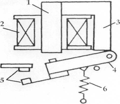 A simple electromagnetic relay is an adaptation of an electromagnet. It consists of a coil of wire (2) surrounding a soft iron core(l), an iron yoke(3), which provides a low reluctance path for magnetic flux, a moveable iron armature (4), spring (6) and a set, or sets, of contacts(5). The armature is hinged to the yoke and mechanically linked to a moving contact or contacts. It is held by a spring so that when the relay is deenergised there is an air gap in the magnetic circuit. In this condition, one of the two sets of contacts is closed, and the other set is open. Other relays may have more or fewer sets of contacts depending on their function.
When an electric current is passed through the coil, the resulting magnetic field attracts the armature, and the consequent movement of the movable contact or contacts either makes or breaks a connection with a fixed contact. If the set of contacts was closed when the relay was deenergised, then the movement opens the contacts and breaks the connection, and vice versa if the contacts were open. When the current to the coil is switched off, the armature is returned by a force, approximately half as strong as the magnetic force, to its relaxed position. Usually this force is provided by a spring, but gravity is also used commonly in industrial motor starters. Most relays are manufactured to operate quickly. In a low voltage application, it is used to reduce noise, in a high voltage or high current application, it is used to reduce arcing.
Linear motors
The first linear motor was conceived by Wheatstone more than a hundred years ago. But large air gaps and low efficiencies prevented linear motors from being widely used. Though they still have relatively large air gaps, linear induction motors are increasingly chosen for material-handling applications because they are quieter, more reliable, and less expensive than rotary motors. And because linear motors do not drive gearboxes or rotary-to-linear conversion devices, they can be more efficient.
A linear motor is conceptually a rotary motor whose stator core has been cut and unrolled. The circular stator becomes a linear stator, defining a single-sided linear induction motor (SLIM). Likewise, if the circular stator is cut into two sections and flattened, the motor becomes a double sided linear induction motor (DLIM). The DLIM and SLIM both require a two or three-phase stator (primary) winding and a flat metallic or conductive plate-type armature (secondary). Cutting and unrolling the stator leads to many other possible linear motor configurations. For example, a tubular motor can be conceptually made from the SLIM by rerolling it in the direction of motion. The pole pattern is produced by three-phase windings in alternate clockwise and counter-clockwise directions around the tube. Other designs are also possible, but few of them are used.
There are several important differences between linear and rotary induction motors that bear on selection. Unlike rotary motors, the linear motor has a beginning and an end to its travel.
First, the moving secondary material enters the primary at one end of the motor and exits at the opposite end. Induced currents in the secondary material at the entry edge resist air gap flux buildup. And at the exit edge, the material retards the air gap flux decay. This results in an uneven air gap flux distribution. Such flux distribution causes little or no thrust under the first few poles at entry and a braking thrust at exit.
At stall and low speeds, the flux distribution is not seriously distorted and is usually ignored. Second, the large air gap which is endemic to linear motors effectively limits linear force. Fortunately, new pole piece designs offset the adverse air-gap effect.
The moving member in a linear motor is typically a solid conducting plate or sheet. It does not contain coils or windings.
A normal force between stator and armature in the SLIM is perpendicular to the direction of travel. The stator and armature are either attracted or repelled by this force. Factors that determine the force direction include armature material composition and thick-ness, stator frequency, air gap, and pole pitch. SLIMs are constructed to minimize the normal force. For DLIMs, rotary, and tubular motors, these forces cancel.
Recent advances in power electronics, microprocessors, and electro-magnetic analysis software are responsible for many new linear-motor designs. Power electronics provide inexpensive pulse-width modulators (PWMs), vector controllers, and variable frequency drives. Microprocessors used for control include 32-bit processors, coprocessors and digital signal processors (DSPs).
Brushless DC electric motor
1. Design different between brush and brushless DC motor
A brushless DC motor (BLDC)is a synchronous electric motor which is powered by direct-current electricity (DC) and which has an electronically controlled commutation system, instead of a mechanical commutation system based on brushes. In such motors, current and torque, voltage and rpm are linearly related.
In a conventional (brushed) DC motor, the brushes make mechanical contact with a set of electrical contacts on the rotor (called the commutator),forming an electrical circuit between the DC electrical source and the armature coil-windings. As the armature rotates on axis, the stationary brushes come into contact with different sections of the rotating commutator. The commutator and brush system form a set of electrical switches, each firing in sequence, such that electrical-power always flows through the armature coil closest to the stationary stator (permanent magnet).
In a BLDC motor, the electromagnets do not move; instead, the permanent magnets rotate and the armature remains static. This gets around the problem of how to transfer current to a moving armature. In order to do this, the brush-system/ commutator assembly is replaced by an electronic controller. The controller performs the same power distribution found in a brushed DC motor, but using a solid-state circuit rather than a commutator/brush system.
2. Comparison with brushed DC motors
Because of induction of the windings, power requirements, and temperature management some glue circuitry is necessary between digital controller and motor.
BLDC motors offer several advantages over brushed DC motors, including higher efficiency and reliability, reduced noise, longer lifetime (no brush erosion), elimination of ionizing sparks from the commutator, and overall reduction of electromagnetic interference (EMI). With no windings on the rotor, they are not subjected to centrifugal forces, and because the electromagnets are located around the perimeter, the electromagnets can be cooled by conduction to the motor casing, requiring no airflow inside the motor for cooling. This in turn means that the motor’s internals can be entirely enclosed and protected from dirt or other foreign matter. The maximum power that can be applied to a BLDC motor is exceptionally high, limited almost exclusively by heat, which can damage the magnets. BLDC’s main disadvantage is high cost, which arises from two issues. First, BLDC motors require complex electronic speed controllers to run. Brushed DC motors can be regulated by a comparatively trivial variable resistor (potentiometer or rheostat), which is inefficient but also satisfactory for cost-sensitive applications. Second, many practical uses have not been well developed in the commercial sector. For example, in the RC hobby scene, even commercial brushless motors are often hand-wound while brushed motors use armature coils which can be inexpensively machine-wound.
BLDC motors are considered to be more efficient than brushed DC motors. This means that for the same input power, a BLDC motor will convert more electrical power into mechanical power than a brushed motor, mostly due to the absence of friction of brushes. The enhanced efficiency is greatest in the no-load and low-load region of the motor's performance curve. Under high mechanical loads, BLDC motors and high-quality brushed motors are comparable in efficiency.
3. Controller implementations
Because the controller must direct the rotor rotation, the controller needs some means of determining the rotor’s orientation/position (relative to the stator coils.) Some designs use Hall-effect sensors or a rotary encoder to directly measure the rotor’s position. Others measure the back EMF in the undriven coils to infer the rotor position, eliminating the need for separate Hall-effect sensors, and therefore are often called “sensorless” controllers.
The controller contains 3 bi-directional drivers to drive high-current DC power, which are controlled by a logic circuit. Simple controllers employ comparators to determine when the output phase should be advanced, while more advanced controllers employ a microcontroller to manage acceleration, control speed and fine-tune efficiency. Controllers that sense rotor position based on back-EMF have extra challenges in initiating motion because no back-EMF is produced when the rotor is stationary. This is usually accomplished by beginning rotation from an arbitrary phase, and then skipping to the correct phase if it is found to be wrong. This can cause the motor to run briefly backwards, adding even more complexity to the startup sequence.
4. Variations on construction
BLDC motors can be constructed in several different physical configurations: in the “conventional” (also known as “inrunner”) configuration, the permanent magnets are mounted on the spinning armature (rotor). Three stator windings surround the rotor. In the “outrunner” configuration, the radial-relationship between the coils and magnets is reversed; the stator coils form the center (core) of the motor, while the permanent magnets spin on an overhanging rotor which surrounds the core. The flat type, used where there are space or shape limitations, uses stator and rotor plates, mounted face to face. Outrunners typically have more poles, set up in triplets to maintain the three groups of windings, and have a higher torque at low RPMs. In all BLDC motors, the stator-coils are stationary.
There are also two electrical configurations having to do with how the wires from the windings are connected to each other (not their physical shape or location). The delta configuration connects the three windings to each other in a triangle-like circuit, and power is applied at each of the connections. The wye (“Y”-shaped) configuration, sometimes called a star winding, connects all of the windings to a central point (parallel circuits) and power is applied to the remaining end of each winding.
A motor with windings in delta configuration gives low torque at low rpm, but can give higher top rpm. Wye configuration gives high torque at low rpm, but not as high top rpm.
Although efficiency is greatly affected by the motor’s construction, the wye winding is normally more efficient. Delta-connected windings can allow high-frequency parasitic electrical currents to circulate entirely within the motor. A wye-connected winding does not contain a closed loop in which parasitic currents can flow, preventing such losses.
From a controller standpoint, the two styles of windings are treated exactly the same, although some less expensive controllers need to read voltage from the common center of the wye winding.

| 
|
| Spindle motor from a 3.5" floppy disk drive | The poles on the stator of a two-phase BLDC motor. This is part of a computer cooling fan; the rotor has been removed |
5. Applications
BLDC motors can potentially be deployed in any area currently fulfilled by brushed DC motors. Cost and control complexity prevents BLDC motors from replacing brushed motors in most common areas of use. Nevertheless, BLDC motors have come to dominate many applications: Consumer devices such as computer hard drives , CD/DVD players, and PC cooling fans use BLDC motors almost exclusively. Low speed, low power brushless DC motors are used in direct-drive turntables . High power BLDC motors are found in electric vehicles, and some industrial machinery. These motors are essentially AC synchronous motors with permanent magnet rotors.
The Honda Civic hybrid car uses a BLDC motor to supplement the output of the internal combustion engine when the extra power is needed. It is also used to start the engine without a starter.
The Segway Scooter also used BLDC technology. A number of electric bicycles use BLDC motors that are sometimes built right into the wheel hub itself, with the stator fixed solidly to the axle and the magnets attached to and rotating with the wheel. The bicycle wheel hub is the motor. This type of electric bicycle also has a standard bicycle transmission with pedals, gears and chain that can be pedaled along with, or without, the use of the motor as need arises.
A BLDC motor power a micro remote-controlled airplane. The motor is connected to a microprocessor-controlled BLDC controller. This 5-gram motor produces more thrust than twice the weight of the entire plane. Being an outrunner, the rotor-can containing the magnets spins around the coil windings on the stator.
Recently, an increase in the popularity of electric-powered model aircraft has spurred demand for high-performance BLDC motors. Many hobbyists have begun salvaging BLDC motors from scrap CD/DVD-ROM drives, refurbishing them for use in radio controlled planes.
Coreless DC Motors
The development of coreless motors dates back to the middle 1930s. But it wasn’t until the early 1960s that they were produced economically enough to gain wide acceptance.
Major advantages of coreless motors include very low inertia, low mechanical time constant, and high efficiency. Because the core is ironless, its low mass allows more rapid acceleration and deceleration than any other class of dc motor.
Other benefits gained by eliminating the iron core include the absence of magnetic fields acting on the laminations. This interaction in conventional motors appears as torque ripple or cogging plus a resisting torque that decreases motor efficiency. The absence of iron eliminates cogging and the coreless motor operates smoothly, even at low speeds.
Elimination of the iron core dramatically diminishes rotor inductance and resultant arcing. Commutator arcing in conventional motors is caused primarily by the release of stored energy in the armature inductance upon commutation. Excessive arcing produces electrical noise and reduces the life of brushes.
Coreless motors are classified by rotor shapes as cylindrical or disc. Cylindrical rotors are further divided into those containing inside fields or outside fields. The disc types have pancake, printed, or three-coil rotors.
The cylindrical outside-field motor has the smallest mechanical time constant. The stator is a cylindrical permanent magnet surrounded by a mild steel housing. The rotor is a hollow cylindrical coil wound of copper wire and located in the center of the stator. A mechanical time constant of 1 msec is not unusual for this type of motor.
Rotors are typically wound in a skewed or honeycomb pattern (also known as Faulhaber winding) to ensure that all of the core helps produce torque and smooth operation. The flux lines extend radially outward from the pennanent-magnet stator through the air gap. The soft iron housing is the flux return path which allows the air gap to be extremely small, producing a high flux density.
The cylindrical inside-field motor is a similar design, but the permanent-magnet stator is located inside the hollow rotor. The motor also features a low moment of inertia, but the mechanical time constant is typically higher than the outside-field motor because of smaller stator magnets.
Coreless motor commutators and brushes are typically small, primarily because they are made of precious metals-gold, silver, platinum, or palladium. In addition, a smaller commutator has lower peripheral speed, less wear, and accounts for a smaller motor.
Outside-field motors are usually selected for high acceleration. Because of this, the rotor coils must handle a large load torque and dissipate high heat produced by peak currents. To handle the torque, manufacturers strengthen the rotor with glass epoxy. Since the rotor does not have an iron core to act as a heat sink, the housing has ports for forced air cooling.
In any electric motor, operation is based on simple electromagnetism. A current-carrying conductor generates a magnetic field; when this is then placed in an external magnetic field, it will experience a force proportional to the current in the conductor, and to the strength of the external magnetic field. As you are well aware, when opposite (North and South) polarities attract, while like polarities (North and North, South and South) repel. The internal configuration of a DC motor is designed to harness the magnetic interaction between a current-carrying conductor and an external magnetic field to generate rotational motion.
Every DC motor has six basic parts-axle, rotor, stator, commutator, field magnets and brushes. In most common DC motors the external magnetic field is produced by high-strength permanent magnets. The stator is the stationary part of the motor; this includes the motor casing, as well as two or more permanent magnet pole pieces. The rotor (together with the axle and attached commutator) rotates with respect to the stator. The rotor consists of windings, the windings being electrically connected to the commutator.
The geometry of the brushes, commutator contacts and rotor windings are such that when power is applied, the polarities of the energized winding and the stator magnets are misaligned and the rotor will rotate.
Classification of A.C. Motors
With the almost universal adoption of a.c. system of distribution of electric energy for light and power, the field of application of a.c. motors has widened considerably during recent years. As a result, motor manufacturers have tried, over the last few decades, to perfect various types of a.c. motors suitable for all classes of industrial drives and for both single and three-phase a.c. supply. This has given rise to bewildering multiplicity of types whose proper classification often offers considerable difficulty. Different a.c. motors may, however, be classified and divided into various groups from the following different points of view:
1. PRINCIPLE OF OPERA TION
(A)Synchronous motors
(i) plain and (ii) super
(B)Asynchronous motors
(a) Induction motors
Squirrel-cage single – double
(b) Commutator motors
(i) Series – single-phase – universal
(ii) Compensated – conductively- inductively
(iii) Shunt – simple – compensated
(iv) Repulsion – straight- compensated
(v) Repulsion-start induction
(vi) impulsion induction
2. THE TYPE OF CURRENT
(i) single phase
(ii) three phase
3. SPEED
(i) constant speed
(ii) variable speed
(Hi) adjustable speed
4. STRUCTURAL FEA TURES
(i) open (ii) enclosed (Hi) semi-enclosed (iv) ventilated (v) pipe-ventilated (vi) riveted frame eye
Induction Motor : General Principle
As a general rule, conversion of electrical power into mechanical power takes place in the rotating part of an electric motor. In dc motors, the electrical power is conducted directly to the armature (i.e. rotating part) through brushes and commutator. Hence, in this sense, a dc motor can be called a conduction motor. However, in ac motors, the rotor does not receive electric power by conduction but by induction in exactly the same way as the secondary of a 2-winding transformer receives its power from the primary. That is why such motors are known as induction motors. In fact, an induction motor can be treated as a rotating transformer i. e. one in which primary winding is stationary but the secondary is free to rotate.
Of all the a.c. motors, the polyphase induction motor is the one, which is extensively used for various kinds of industrial drives. It has the following main advantages and also some disadvantages.
Advantages:
1. It has very simple and extremely rugged, almost unbreakable construction (especially squirrel-cage type).
2. Its cost is low and it is very reliable.
3. It has sufficiently high efficiency. In normal running condition, no brushes are needed hence fractional losses are reduced. It has a reasonably good power factor.
4. It requires minimum of maintenance.
5. It starts up from rest and needs no extra starting motor and has not to be synchronised. Its starting arrangement is simple especially for squirrel-cage type motor.
Disadvantages :
1. Its speed cannot be varied without sacrificing some of its efficiency.
2. Just like a d.c. shunt motor, its speed decreases with increase in load.
3. Its starting torque is somewhat inferior to that of a d.c. shunt motor.
Дата добавления: 2014-11-13; просмотров: 502; Мы поможем в написании вашей работы!; Нарушение авторских прав |