КАТЕГОРИИ:
АстрономияБиологияГеографияДругие языкиДругоеИнформатикаИсторияКультураЛитератураЛогикаМатематикаМедицинаМеханикаОбразованиеОхрана трудаПедагогикаПолитикаПравоПсихологияРиторикаСоциологияСпортСтроительствоТехнологияФизикаФилософияФинансыХимияЧерчениеЭкологияЭкономикаЭлектроника
CRUISE POWER CHART
CRUISE POWER CHART V
A.U.W. Г BASIC WT LESS ONE PILOT PAY-
WEIGHTS FUEL LOAD
FOR LOIL
I! 11 i I! 1111111!! и 11! 11111! 111 s: lii;!lijiili:i!|nli PRESS. ALTITUDE: 5,000 FT;t
| FUEL ALLOWANCE 10 MIN. WARM-UP & TAKE-OFF CLIMB TO 5,000 FT FUEL FOR 45 MIN. FLIGHT AT CRUISE POWER (г40 ВНР) IN RESERVE |
| I !!|j|l!IS!ill!IIIIIM!lltill!ll!llll SPEED: 125 MPH (TAS) |
| POWER: 240 ВНР |
i[||ll!llllllli!i"lHTi^lijlHiHiTnni!;l:i]i[i!'il
| и > Г О > О < сл |
| г > |
| ТЭ 5 С й 5 о jo > 2 О М |
FUEL REQUIRED
Ji 300 I I 400 <1 \ 500 CRUISING RANGE (STAT. MILES)
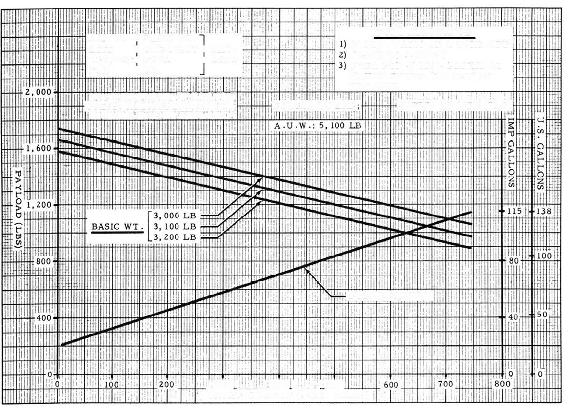
| FUEL OIL ONE PILOT BASIC WEIGHT |
| PAYLOAD - A.U.W. LESS |

FUEL ALLOWANCE
10 MIN. WARM-UP Ac TAKE-OFF CLIMB TO 5,000 FT. FUEL FOR 45 MIN. FLIGHT AT CRUISE POWER IN RESERVE.
| PRESS. ALTITUDE: 5,000 FT |
| POWER: 240 BHF |
CRUISING SPEED (TAS): 1 14 MPH
тз >
<
г
о >
о
VI
CI V
> О
> к
И Z
с
РЗ >
| BASIC WEIGHT |
2 О tn
FUEL REQUIRED
| < £ |
CRUISING RANGE (STAT. MILES)
| SAFE MOMENTS LIMITS | |||||
| Gross Weight | Landplane and Skiplane | Seaplane | |||
| Forward | Aft (See Note) | Forward | Aft | ||
| Column A | Column В | ||||
| +19800 | -23100 | -26400 | +19800 | - 18300 | |
| +20500 | -23900 | -27300 | +20500 | -18900 | |
| +21100 | -24600 | -2Б200 | +21100 | -19500 | |
| +21800 | -25400 | -25000 | +21800 | -20100 | |
| +22400 | -26200 | -25500 | +22400 | -20700 | |
| +23100 | -27000 | -30800 | +23100 | -21400 | |
| +23800 | -27700 | -31700 | +23800 | -22000 | |
| +24400 | -28500 | -32600 | +24400 | -22600 | |
| +25100 | -29300 | -33400 | +25100 | -23200 | |
| +23400 | -30000 | -34300 | +23400 | -23800 | |
| +21600 | -30800 | -35200 | +21600 | -24400 | |
| +19600 | -31600 | -36100 | +19600 | -25000 | |
| +17600 | -32300 | -37000 | +17600 | -25600 | |
| +15400 | -33100 | -37800 | +15400 | -26200 | |
| +13100 | -33900 | -38700 | + i3100 | -26800 | |
| +10700 | -34600 | -39600 | +10700 | -27400 | |
| + 8100 | -35400 | -40500 | ^ 8100 | -28100 | |
| + 5500 | -36200 | -41400 | + 5500 | -28700 | |
| + 2700 | -37000 | -42200 | + 2700 | -29300 | |
| - 200 | -37700 | -43100 | - 200 | -29900 | |
| - 3200 | -38500 | -44000 | - 3200 | -30500 | |
| - 6000 | -31100 | ||||
| •» — «. — «в » | |||||
| - 6400 | -39300 | -44900 | |||
| FREIGHT | ||
| Weight lb. | Mom . in . lb . | |
| Fwd .Arm | Aft Arm | |
| -19 in. | -57 in. | |
| - 475 | - 1425 | |
| - 950 | - 2850 | |
| - 1425 | - 4275 | |
| - 5700 | ||
| - 3800 | -11400 | |
| - 5700 | -17100 | |
| - 7600 | -22800 | |
| - 9500 | -28500 | |
| -11400 | -34200 | |
| -13300 | -39900 | |
| - 15200 | -45600 | |
| -17100 | -51300 | |
| -19000 | -57000 | |
| -20900 | -62700 | |
| -22800 | -68400 | |
| -23750 | -71250 |
| FUEL | ||
| BELLY TANK | ||
| Capacity = 36 I.G. | ||
| A rm | = -8.0 in. | |
| Imp. | Wgt. | Mom |
| Gal. | lb. | in. lb. |
| - 576 | ||
| - 1152 | ||
| -1728 | ||
| -2072 |
FLOOR STRENGTH___________
For uniformly distributed load
100 lb/sq.ft. For concentrated load (penetration strength)
200 lb/sq.ft.
NOTE
SAFE MOMENT LIMITS - AFT Land and Ski Plane COLUMN A Applies to aircraft in which the rigging recommendations outlined in Engineering Bulletin Series В No. 1 have not been incorporated.
COLUMN В Applies to aircraft in which the rigging recommendations outlined in Engineering Bulletin Series В No. 1 have been incorporated.
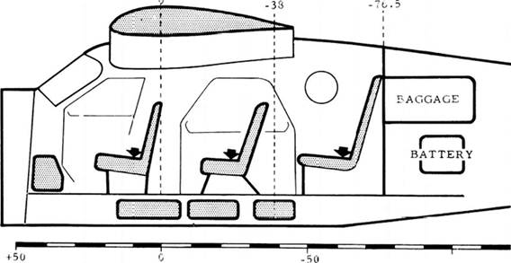
BASIC WEIGHT OF AIRCRAFT. . . . LB* BASIC MOMENT *
PILOT/PASSENGER STD . WEIGHT 170 LB.
(Insert actual weight and basic ;noincnt given in weight and balance report found in envelope on inside of rear cover)
| ARM IN INS. | + 7 | -29 | -62 | |
| MOMENT | + 1190 | -4930 | -10540 | |
| CARGO MEAN ARM | IN INS. | * FORE -19 | AFT -57 | |
| LITTER = -33 (PATIENT INCL.)-8250 |
 - 100
- 100
|
ADD TO BASIC WEIGHT AND TO BASIC MOMENT
A. PILOT(S) AND PASSENGER(S)
B. FREIGHT AND BAGGAGE

|
| WEIGHTS AND MOMEN!S |
C. FUEL AND OIL
OIL TANK
CAP. 5.2 ARM
| MOM |
| 18 36 46.8 |
IMP. GAL. +37 .u IX .
GAL. L1»
+ 666 + 1332 + 1732
A. TAKE OFF WEIGHT IS NOT OYER 5, 100 Lb .
B. TOTAL MOMENT VALUE IS WITHIN SAFF. MOMENT LIMITS.
| 2) MAKE SURE: |
C. AVAILABLE TAKE OFF DISTANCE PERMITS TAKE-OFF AT THIS WF.IGiiT.
CAP. IMP.GAL. GAL. LB.
| 5 10 15 20 JS 2° |
~3o
{J. 108 144
| ' FRONT TANK 4 |
| ARM + 4.^ IN . MOM + 1(»2 + 324 + 48o + 648 + 810 + <40 |
ISO 2CW
CENTRE
| TANK ARM - 19.6 IN . |
| 1. x 1 |
CAP. 29 IMP. GAL.
| GA L. | LB. | MOM |
| - 70o | ||
| ! 0 | -1411 | |
| -2117 | ||
| -2822 | ||
| -3528 | ||
| 20V | -4 0°o |
| С REAR | TANK ^ | |
| CAP | 2 1 | ARM |
| IMP. | GAL | -40.0 IN . |
| GA L | LB . | MOM |
| - 1440 | ||
| i 1 w | -2880 | |
| 1 v/8 | -4320 | |
| ->, • | -5760 | |
| U1 | . 5 i | -6040 |
| О . :.: 1 |
| BAGGAGE COMPI | |
| ARM | -94.0 IN'. |
| LB . | MOM |
| -23*0 | |
| -4700 | |
| -70S0 |
'JS G
VIII OPERATIONAL LOADS DIAGRAM
Supplement No 1 FLIGHT MANUAL
AIRCRAFT
| 15 APRIL 1959 |
Agricultural Installations
15 April 1959
SUPPLEMENT 1
AGRICULTURAL INSTALLATIONS
TABLE OF CONTENTS
PARAGRAPH No. TITLE PAGE
1 GENERAL Sl-1
2 AGRICULTURAL MODEL Sl-1
2.1 FEEDER AND SEEDER INSTALLATION Sl-1
2.2 SPRAYER INSTALLATION Sl-1
2.3 ALTERNATIVE SPRAYER INSTALLATION Sl-1
2.4 SUPPLY DROPPING INSTALLATION S1 -4
3 SPRAYER MODEL Sl-5 3.1 SPRAYER INSTALLATION Sl-5
4 OPERATION Sl-5
4.1 OPERATING LIMITS Sl-7
4.2 WEIGHT AND MOMENT TABLE Sl-7
4.3 OPERATIONAL TABLES Sl-9
LIST OF ILLUSTRATIONS
FIGURE TITLE PAGE
Sl-1 FEEDER AND SEEDER INSTALLATION SI-2
S1 -2 AGRICULTURAL MODEL SPRAYER
INSTALLATION Sl-3
Sl-3 ALTERNATIVE SPRAYER INSTALLATION SI-4
S1 -4 SUPPLY DROPPING INSTALLATION Sl-5
Sl-5 SPRAYER MODEL INSTALLATION Sl-6
AGRICULTURAL INSTALLATIONS
1. GENERAL
The de Havilland agricultural installations are fitted to two types of Beaver aircraft, one being a special version of the Beaver Landplane known as the Agricultural model and the other a Standard Beaver Land- plane, seaplane or amphibian known as the Sprayer model.
2. AGRICULTURAL MODEL
The equipment fitted to the agricultural model comprises a feeder and seeder installation for fertilizer and seeder application, a sprayer installation for crop spraying, and wing mounted external racks for supply dropping. Removable seats are provided for a loading crew of three, to be used when ferrying from base to dropping zone. Conversion to any of these roles can be accomplished readily.
NOTE
Range and endurance are reduced by approximately 33% of those stated in para. 4.10.1 of the Flight Manual, since the agricultural model is not fitted with a centre fuel tank.
2.1 Feeder and Seeder Installation
(See Figure Sl-1) This installation consists of a 35 cubic foot capacity hopper which protrudes through the cabin floor and fuselage skin to an unloading chute operated by a lever at the right side of the pilot's seat. A roof hatch facilitates loading of the hopper. An emergency release catch, located aft of the chute and operated by a push button on the left grip of the pilot's control wheel, enables the entire hopper load to be jettisoned in a few seconds.
2.2 Sprayer Installation
(See Figure SI-2} The sprayer installation consists of the hopper, with a rubber bag inserted to contain the fluid, and a sump in place of the chute used on the feeder and seeder installation. The liquid capacity of the hopper is 220 Imperial (265 U.S.) gallons, the liquid contents being released by means of a spray control lever located immediately to the left of the engine controls quadrant. Adjacent to the control lever is an adjustable stop, which can be locked at a pre-determined position with a pip-pin, enabling movement of the control lever to be limited according to the desired amount of fluid flow.
The fluid contents are jettisonable in an emergency by depression of a push button on the left grip of the pilot's control wheel which allows a jettison door to open on the sump. A wind-driven centrifugal pump and valve system, mounted on the centre line of the aircraft forward of the sump, feeds fluid under pressure to a span length spray boom extending laterally from the pump. The boom sections, attached to the wings by vee struts and to the fuselage by brackets, can be equipped with tee jet or whirl jet type nozzles as required by the operator. To prevent over-spraying or loss of fluid, the boom incorporates diaphragm check valves which close when the fluid pressure drops below 7 psi. A pressure gauge is connected to the boom to provide the pilot with visual indication of the fluid pressure being supplied to the boom and spray nozzles when the system is in operation. An idling circuit is incorporated in the valve system so that an excessive fluid pressure will not be imposed in the boom or spray nozzles. For ferrying flights, the boom sections can be stowed under the rear fuselage.
2.3 Alternative Sprayer Installation
(See Figure Sl-3)
An alternative sprayer installation to the span length boom utilizes two ICD rotor units, giving a swath width and concentration less than the boom installation. The gravity fed rotor unite are fitted to the ends of the spray booms which are braced to the airframe and extend late rally from the sump, terminating outboard of the propeller arc. Each ICD rotor unit consists of a wind-driven fan at the forward end of a rotor shaft, with a wire brush at the aft end which disperses the fluid from the rotor unit in droplets, at a controllable rate of 1 to 50 gallons per minute, into the airstream. The rate of dispersal of the fluid is dependent on the selected position of the spray control lever in the cockpit, the size of the wire brushes, rotor unit valve opening and the pitch and diameter of the fans which determine the rotational speed of the rotors.
| HOPPER |
| LOADING HATCH (IN CABIN ROOF) |
| CHUTE OPERATING LEVER |
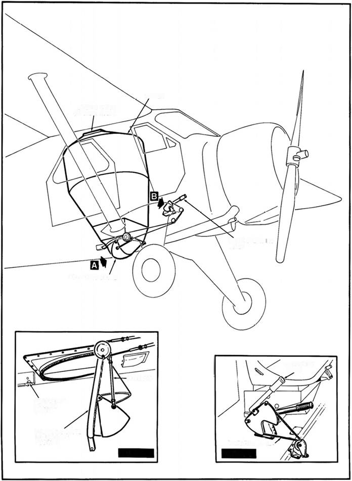
UNLOADING CHUTE
OPERATING LEVER
PUSH ROD
EMERGENCY
RELEASE
| OPERATING CABLE |
CATCH
UNLOADING CHUTE IN JETTISON POSITION
| DETAIL В |
DETAIL A
FIG Sl-1 FEEDER AND SEEDER INSTALLATION

|
FIG SI-2 AGRICULTURAL MODEL SPRAYER INSTALLATION
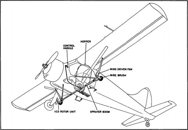 FIG Sl-3 ALTERNATIVE SPRAYER INSTALLATION
|
2. 4 Supply Dropping Installation
(See Figure SI-4}
NOTE
It is essential to check with the airworthiness authority of the State in which the aircraft is operating to ensure that it is permissible to carry or drop stores, using external racks, within the area of their jurisdiction.
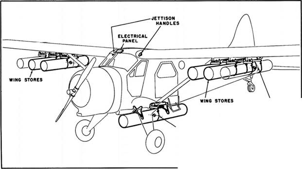
The supply dropping installation consists of up to six Mark III external racks,capable of carrying 300 lb each, mounted three each side of the wing under surface and outboard of the wing attachment struts. Alternatively, an installation consisting of four lightweight wing racks with a carrying capacity of 250 lb each, and a fuselage ventral rack with a carrying capacity of 1800 lb may be fitted, provided the total weight of the supplies to be dropped doe8 not exceed 1800 lb. Installation of the fuselage rack necessitates removal of the hopper jettison assembly. The fuselage rack may also be fitted in conjunction with the Mark III wing racks provided the total weight of the supplies to be dropped does not exceed 1800 lb. An electrical switch panel in the cabin roof permits selection of any or all of the stores to be dropped. The release of the selected stores is accomplished by depression of the push button on the left grip of the pilot's control wheel, provided that the RACK MASTER switch on the electrical switch panel is ON. In the event of an electrical failure, or in an emergency, the wing stores can be jettisoned by pulling the two jettison handles, one above each cockpit door.
CAUTION
To maintain the lateral trim of the aircraft, the wing stores should be released in handed pairs, never from one side only. Release of all the wing stores at the same time should be restricted to emergency jettisoning.
NOTE
The dimensions of the stores on each wing rack should not exceed 1 ft. diameter nor be longer than 5 ft. 6 inches. The dimensions of the stores on the fuselage rack should not exceed 1 ft. diameter or 7 ft. in length.
3 SPRAYER MODEL
The equipment fitted to the sprayer model (Standard Beaver landplane, seaplane, or amphibian) consists of a sprayer installation and, if equipped with C2-W-587A and 588A type wings, can be used for supply dropping. Removal of the sprayer equipment and replacement of the cabin doors permits conversion to Standard Beaver duties.
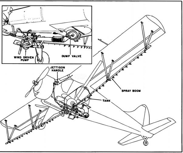
1 1 Sprayer Installation
(See Figure SI-5) The sprayer installation consists of a 200 Imperial (240 U.S.) gallon cylindrical tank mounted athwartships in the cabin from doorway to doorway, necessitating removal of the doors and the fitting of special panels which serve to support the tank and close off the doorways.
A filler neck is on each side of the tank which is connected to forward facing air pressure intakes on top of the fuselage. A pipe at the bottom of the tank allows the contents to pass to a centrifugal wind-driven pressure pump and valve system under the fuselage from which a span length boom originates. The boom sections are similar to those used in the Agricultural model and have similar fittings and furnishings. The liquid contents of the tank are released and controlled by selection of a control valve between the pilot's and co-pilot's seats. The tank can be emptied in an emergency by pulling the jettison handle adjacent to the flight instrument panel, which opens the tank dump valves. A gauge in the forward face of the tank indicates the quantity of fluid in the tank. For ferrying flights the boom sections can be stowed under the rear fuselage.
4. OPERATION
Complete the checks detailed in Section II of the Flight Manual, and before any flight ensure that all equipment is properly secured.
NOTE
| CG POSITION 6* AFT OF FORWARD CHAIN |
| VENTRAL STORE Св POSITION AT CHAIN |
| FIG SI-4 SUPPLY DROPPING INSTALLATION |
Ensure that theC. G. of the external wing
stores is located six inche s aft of the forward anchor chain of each load.
CAUTION
Before any ferrying flight on spray aircraft, the fan of the pump should be removed if there is no far. brake, otherwise the shaft may seize in its bearings.
The recommended airspeed during operation, with flaps at CRUISE, is 100 to 105 mph (87 to 91 knots) IAS with a maximum limit of 120 mph (104 knots) IAS. At 100 mph (87 knots) IAS, a fertilizer or feeder coverage 100 feet by 2000 feet, from an altitude of 100 feet, can be obtained at a rate of 200 to 300 lb per acre which will discharge an 1850 lb load in 10 to 15 seconds.
At an altitude of 10 feet the boom sprayer installation will give a swath width of 90 feet, using 1/2 to 3 1/2gallons of liquid per acre, depending on control lever setting and system pressure. Increase of altitude to 100 feet will increase the swath width to approximately 140 feet.
NOTE
| CONTROL LEVER FIG Sl-5 SPRAYER MODEL INSTALLATION |
|
To improve aircraft handling characteristics when operating at the lower altitude, the flaps can be lowered to CLIMB position and the airspeed reduced to 90 mph (78 knots) IAS. This will provide a higher rate of climb when operating in hilly areas.
CAUTION
It is important to wash out the spray installation daily to prevent corrosion and deterioration caused by the spray fluid. The rear of the aircraft should be washed down after spraying and after crop fertilizing or seeding. Checking for heavy accumulation of dust on the control surfaces and hinges is highly desirable.
The flight altitude during dropping of stores is dependent on local air regulations, the type of stores being dropped, and the surrounding terrain. Normally the air speed should be reduced to 100 mph (87 knots) IAS and the flaps lowered to CLIMB setting before the stores drop is commenced, and altitude reduced to approximately 100 feet above ground level.
4. 1 Operating Limits
The operating limits for the Agricultural modeL and Sprayer model are the same as in Section IV of the Flight Manual except that in the Agricultural model removal of the centre fuel tank, to provide space for the hopper, will reduce the range and endurance by approximately 33%.
| MOMENT TABLE |
4. 2 WEIGHT AND
With the agricultural installations
AGRICULTURAL MODEL
Add to Basic Agricultural Aircraft
For fertilizer and seeder operation:
Hopper assembly - empty
Chute
Cockpit control levere and fittings Total
Hopper - loaded (e.g. 1600 lb) Total as flown
the aircraft basic weight is affected as follows:
Weight Arm Mom
lb in lb in
83 -25.5 -2116
20.8 -20.3 - 422
4 - 3 -____ 12
107.8 -2550
1600 -23.9 -38240
1707.8 -40790
| For spray boom operations, with hopper | installed: | ||
| Hopper assembly - empty | -25.5. | -2116 | |
| Hopper lining and sump | -23 | - 713 | |
| Span length boom | - 8 | - 288 | |
| Wind-driven pump assy, and piping | 30.5 | -16 | - 488 |
| V struts | -12 | - 216 | |
| Cockpit control levers and fittings | - 3 | - 12 | |
| 202.5 | -3833 | ||
| Hopper - loaded (e.g. 160 Imp. gal. water) | -23.9 | -38240 | |
| Total as flown | 1802.5 | -42073 |
| For ICD rotor spray operations, with hopper | installed: | ||
| Hopper assembly - empty | -25.5 | -2116 | |
| Hopper liner and sump | -23 | - 713 | |
| Rotor units (2) plus piping and fitting | 40.8 | -36.9 | -1504 |
| Bracing struts (4) | 9.3 | -16.6 | - 154 |
| Cockpit control levers and fittings | - 3 | - 12 | |
| Total | 168.1 | -4499 | |
| Hopper - loaded (e.g. 160 Imp. gal. water) | -23.9 | -38240 | |
| Total as flown | 1768.1 | -42739 |
| Supplement 1 | |||
| Weight | Arm | Mom | |
| lb | in | lb in | |
| For supply dropping operations, with hopper | installed: | ||
| Hopper assembly - empty | -25.5 | -2116 | |
| External wing rack channels (6) - Mk.III and bracing 12 | - 9 | - 108 | |
| Mk.III rack release (6) | - 4 | - 312 | |
| Cockpit control levers and fittings | - 3 | - 12 | |
| Cockpit rack controls | + 4 | + 60 | |
| Total | -2488 | ||
| External wing racks (6) - loaded | |||
| (300 lb each rack) | - 4 | -7200 | |
| Total as flown | -9688 | ||
| Fuselage rack | -28 | - 84 | |
| Fuselage rack - loaded | -32 | -25600 |
SPRAYER MODEL
For Simplex spray boom operations, with spray tank installed: add to Basic Weight (see note)
|
NOTE
Since some items of equipment are removed from the aircraft before installation of the agricultural equipment, reference to the weight and balance report should be made for correct basic weight and C.G. values.
CAUTION
To ensure that the gross weight of the aircraft does not exceed the gross weight permitted by local licencing authorities, restrict the fuel or cargo load as necessary.
For supply dropping operations, with Simplex spray tank and lightweight wing racks installed:
|
OPERATIONAL TABLES AGRICULTURAL MODEL SPRAYING FLUID WEIGHT & MOMENT Note on Use of Table
The weights and moments shown below are for water. To obtain the weights and moments of the spraying fluid being used, multiply the weights and momenta shown below by the specific gravity of the fluid being used.
| Amount | Weight | Arm | Moment |
| in tank | lb | in | lb in |
| Imp. Gal. | |||
| -20.3 | - 6090 | ||
| -20.4 | - 8160 | ||
| -20.6 | -10310 | ||
| -20.9 | -12540 | ||
| -21.2 | -14810 | ||
| -21.4 | -17140 | ||
| -21.7 | -19530 | ||
| -22.0 | -21980 | ||
| -22.2 | -24410 | ||
| -22.5 | -26970 | ||
| -22.7 | -29490 | ||
| -22.9 | -32067 | ||
| -23.1 | -34644 | ||
| -23.3 | -37221 | ||
| -23.4 | -39798 | ||
| -23.5 | -42375 | ||
| -23.7 | -44952 | ||
| -23.8 | -47529 | ||
| -23.9 | -50106 | ||
| -23.9 | -52683 |
MOMENTS OF POWDER IN HOPPER To determine moment of powder in hopper:
(1) Estimate to what level on the gauge glass the surface of the powder corresponds.
(2) From the above Spraying Fluid table find the moment arm which is given for this reading on the gauge glass.
| auge eadii пр. G |
(3) Multiply the number of pounds of powder in the hopper by this arm to obtain the moment.
WING RACK LOAD MOMENTS Arm = -4.0
VENTRAL RACK LOAD MOMENTS Arm = -32.0
| Total Wt lb |
| Total Wt lb |
Total Moment lb in
Total Moment lb in
| - 1600 - 3200 - 6400 - 9600 -12800 -16000 -19200 -22400 -25600 |
| 50 100 200 300 400 500 600 700 800 |
| 50 100 200 300 400 500 600 700 800 900 1000 1100 1200 1300 1400 1500 1600 1700 1800 |
| - 200 - 400 - 800 -1200 -1600 -2000 -2400 -2800 -3200 -3600 -4000 -4400 -4800 -5200 -5600 -6000 -6400 -6800 -7200 |
SPRAYER MODEL
SPRAYING FLUID WEIGHT & MOMENT
Note on Use of Table
The weights and moments shown below are for water. To obtain the weights and moments of the spraying fluid being used, multiply the weights and moments shown below by the specific gravity of the fluid being used.
Arm of Tank = -28.1
U.S. Gal. Imp. Gal. Weight Moment
Water Water lb lb in
10 8.3 83 - 2332
20 16.7 167 - 4693
30 25.0 250 - 7025
40 33.3 333 - 9357
50 41.6 417 -11718
60 50.0 500 -14050
70 58.3 5Я1 -16382
80 66.6 666 -18715
90 75.0 750 -21075
100 83.3 833 -23407
110 91.6 916 -25740
120 100.0 1000 -28100
| U.S. Gal. | Imp. Gal. | Weight | Moment |
| Water | Water | lb | lb in |
| 108.3 | -30432 | ||
| 116.6 | -32765 | ||
| 125.0 | -35125 | ||
| 133.3 | -37457 | ||
| 141.6 | -39790 | ||
| 150.0 | -42122 | ||
| 158.3 | -44482 | ||
| 166.6 | -46815 | ||
| 175.0 | -49147 | ||
| 183.3 | -51507 | ||
| 191.6 | -53840 | ||
| 200.0 | -56172 |
Example of Use of Table
Suppose spraying fluid has specific gravity of .95
and there are 100 Imp. gal. of fluid in tank.
From the above table 100 Imp. gal. of water weigh
1000 lb and have a moment of -28100.
Thus 100 Imp. gal. of spraying fluid weigh .95 x
1000 = 950 lb and have a moment of .95 x -28100 -
-26695.
WING RACK LOAD MOMENTS
Arm = -4.0
| Total Wt lb |
| Total Wt lb |
Total Moment lb in
Total Moment lb in
| 50 100 150 200 250 300 350 400 450 500 |
| 500 1000 1500 2000 2500 3000 3500 4000 4500 5000 |
| 550 600 650 700 750 800 850 900 950 1000 |
| - 5500 - 6000 - 6500 - 7000 - 7500 - 8000 - 8500 - 9000 - 9500 -10000 |
 - •;• г
|
Дата добавления: 2014-12-23; просмотров: 526; Мы поможем в написании вашей работы!; Нарушение авторских прав |